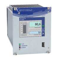
EasyManua.ls Logo

Berthold Duo Xpert User Manual

Berthold Duo Xpert
233 pages
To Next Page IconTo Next Page
Page #1 background imageLoading...
Page #1 background image
Evaluation unit
LB 470 Level
Operating Manual
56925BA2
Rev. No.: 03, 11/2017
Embedded software version as of vers. 1.3.0 (CPU) and 1.3.0 (MU)

Table of Contents

Questions and Answers:

Berthold Duo Xpert Specifications

General IconGeneral
BrandBerthold
ModelDuo Xpert
CategoryControl Unit
LanguageEnglish

Summary

About this Operating Manual

Some Prior Remarks

Provides introductory remarks about the product and manual's scope.

Storage Place

Specifies requirements for storing the operating manual.

Target Group

Identifies the intended audience for the operating manual.

Validity of the Operating Manual

Defines the period of validity for the operating manual.

Structure of the Operating Manual

Explains the organization and chapter breakdown of the manual.

Copyright

States the copyright protection and reproduction restrictions.

Representation

Explains the identifiers, meanings, and examples used in the manual.

Warning notes

Details the structure and types of warning notes in the manual.

Symbols Used in the Operating Manual

Defines the symbols for DANGER, WARNING, and CAUTION.

Symbols Used on the Device

Explains the meaning of symbols found on the device itself.

Conformity

Declares compliance with relevant EU directives.

Safety

Dangers and safety measures

General instructions for reading and storing the manual.

Proper Use

Defines the intended purpose and constraints for the evaluation unit.

Qualification of the Personnel

Specifies the required qualifications for personnel working with the device.

Operator's Obligations

Outlines the responsibilities of the product operator.

System Description

Overview

Introduces the level measuring device and its system components.

Measuring Principle

Explains the radiometric principle used for level measurement.

System Components

Details the various components of the measuring system.

Software

Describes the pre-installed software and its version.

Front/rear view master EVU

Illustrates and describes the front and rear views of the master EVU.

Front/rear view slave module

Illustrates and describes the front and rear views of the slave module.

Type plate

Explains the information provided on the device's type plate.

Measurement arrangements

Describes different setup configurations for measurement.

Storage

Provides guidelines for proper storage of the devices.

Installation

General Instructions

Provides general guidelines and notices for installation.

Unpacking/Scope of Delivery

Details the procedure for unpacking and checking the delivery.

Installation variants

Describes different installation options like wall housings and subracks.

Installation in the wall housing

Provides instructions for installing modules within a wall housing.

Installation in the 19" subrack

Provides instructions for installing modules within a 19" subrack.

Electric Installation

General Instructions

Safety instructions and general points for electrical installation.

Circuit Breaker

Requirements and placement guidelines for circuit breakers.

Cables and Lines

Guidelines for connecting and routing cables safely.

Cable Glands and Blanking Elements

Instructions for using cable glands and blanking elements.

Protective earth and equipotential bonding

Procedures for connecting protective earth and equipotential bonding.

EIA-485 (RS-485) Network

Configuration details for integrating units into an RS-485 network.

Electric connection in the wall housing

Step-by-step guide for electrical connections in a wall housing.

Electrical connection in a 19" subrack with terminal board

Instructions for electrical connections in a 19" subrack using terminal boards.

Terminal board master/master

Pin assignment details for the master/master terminal board.

Terminal board master/slave

Pin assignment details for the master/slave terminal board.

Electrical connection in the 19" subrack with clamp block

Instructions for electrical connections in a 19" subrack using clamp blocks.

Assignment terminals master/slave plug

Details the pin assignments for the master/slave plug.

Assignment clamp block master EVU

Provides the signal and pin assignments for the clamp block master EVU.

Assignment clamp block slave module

Provides the signal and pin assignments for the clamp block slave module.

Operation of the Software

System start

Describes the initial startup screen and software version display.

EVU standard display

Explains the default display screen of the EVU.

Navigation

Illustrates the icons used for navigating through the device menus.

Diagram display

Details how to switch between and view diagrams.

Status messages

Explains the meaning of different status indicators and symbols.

Event reports

Describes how events are displayed and how to view detailed information.

Input field

Explains the functionality and layout of the on-screen keyboard.

Main Menu Device Setup

Menu identification

Allows viewing and changing location name and device information.

Location

Explains how to display and edit the device's location name.

Device information

Provides information about hardware and software versions.

Menu Access

Allows setting user rights and passwords for system protection.

Menu Setup

Provides access to various setup menus for the device.

System (Date / Time, Interfaces, Units, Network, Reset)

Configuration settings for system parameters like date, time, and network.

Interfaces

Settings related to local display, brightness, touch, language, and remote control.

Local Display

Configuration options for the local display settings.

Brightness / Timeout

Adjusts display dimming and timeout settings.

Input / Touch

Guides through calibrating the touch screen for accurate input.

Language

Allows changing the system language.

CE Remote Control

Enables operation of the unit via network connection.

Units

Allows selection of units for measuring values.

Network

Configuration settings for network addresses and DHCP.

Sensors

Allows managing detector configurations and settings.

Detector configuration

Procedure for adding, removing, and configuring detectors.

Detector Settings

Details on editing detector settings like role, type, and description.

Configure a cascaded system

Instructions for configuring detectors in a cascaded system.

Detector settings: Overview

Displays detector parameters and measured values.

Detector settings: Plateau

Information on detector stability and plateau measurement.

Plateau Settings

Allows adjustment of HV start/stop, HV step, and measuring time.

Perform Plateau Measurement

Procedure for conducting a plateau measurement.

Plateau Table

Displays measurement data points and allows export.

Plateau Curve

Shows the characteristic curve of the last complete plateau measurement.

Detector settings: Temperature

Displays current and extreme detector temperature values.

Detector settings: High Voltage

Allows selection of detector code and HV settings.

Detector settings: High Voltage | Detector Type

Settings for the scintillator type and detector code.

Detector settings: High voltage | HV Settings

Configuration options for HV mode, default, and nominal values.

Make HV settings

Procedure for setting HV mode and default values.

Detector settings: Detector Service

Access to device information, event logs, and reset options.

Detector settings: Service | Device information

Displays detector type and software version information.

Perform firmware update

Instructions for updating the detector firmware.

Detector settings: Service | Event Log

Displays the last 25 logged events for the detector.

Detector settings: Detector Service | Event Overview

Presents logged events chronologically in a tabular format.

Detector settings: Detector Service | Reset Detector

Allows restarting or resetting the detector to factory settings.

Calibration

Menu for selecting calibration methods and adapting the system.

Basic Setup

Configuration for calibration methods like linear or point exponential.

Calibration Settings: Background

Procedure for determining background radiation count rate.

Determine background

Steps to measure background radiation and set count rate.

Calibration Settings: Nuclide

Allows selection of the isotope used and its half-life.

Calibration Settings: Table (linear calibration type)

Defines calibration points for linear type.

Add new calibration point

Procedure for adding new calibration points to the table.

Calibration Settings: Table (2 Point Exp. calibration type)

Defines calibration points for 2-point exponential type.

Add new calibration point

Procedure for adding new calibration points to the table.

Calibration Settings: Table (1 Point Exp. calibration type)

Defines calibration points for 1-point exponential type.

Add new calibration point

Procedure for adding new calibration points and calculating the second point.

Calibration Settings: Chart

Displays the characteristic curve of the performed calibration.

Calibrate

Initiates the calibration process, transferring settings to the measurement set.

Recall

Allows copying the measurement set into the calibration set.

Recall to calibration set

Procedure to overwrite measurement parameters with calibration settings.

Adjust: Standard Adjust

Adjusts the calibration table after source exchange or theoretical calibration.

Adjust: Low Level Adjust

Performs a level adjustment at levels below 50%.

Adjust: High Level Adjust

Performs a level adjustment at levels above 50%.

GPC

Configuration for Gas Properties Compensation (GPC).

GPC calibration

Adaptation of the measurement system for gas density compensation.

GPC calibration: Reference count rate

Procedure to determine the reference count rate for GPC.

GPC calibration: Background

Procedure to determine the background radiation for GPC.

GPC calibration: Factor M

Determines the manual correction factor (M) for complex applications.

Capturing the count rates

Procedure for capturing count rates for factor M calculation.

Calculate Factor M

Calculates the correction factor M from the count rate.

GPC calibration: Max. GPC Factor

Sets the maximum compensation factor for level count rate.

GPC settings

Allows selection of isotope for gas density measurement.

Reset GPC Settings

Resets all GPC settings to their default values.

Measurement

Provides an overview of measurement parameters and calibration settings.

Measurement: Parameter

Displays the parameters used for the current measurement.

Measurement: Table

Lists the measurement points used in the current measurement.

Measurement: Chart

Displays the characteristic curve of the current measurement.

Signal Condition

Settings for signal processing like damping and PV range.

Signal processing: Damping

Adjusts the reaction time of the measured value display.

Signal Condition: PV Range

Sets the lower and upper limits of the process range for analog output.

Signal Condition: Rapid Switch

Enables rapid signal adaptation for specific applications.

Signal processing: XIP (Radiation Interference)

Allows consideration of interference effects on measurement.

Signal processing: Source replacement

Enables notification for source replacement.

Setting source replacement date

Sets the date for triggering the source replacement notification.

Inputs

Configuration and status display of digital inputs (DI).

Digital inputs (DI) Assignment

Assigns functions to be executed by digital inputs.

DI State

Displays the current states (ACTIVE/PASSIVE) of digital inputs.

Outputs

Settings for analog and digital outputs.

Analogue Output Mapping (AO)

Assigns functions and values to analog outputs.

Analogue output: AO Mapping

Details how to assign process values or count rates to analog outputs.

Analogue output: AO Monitoring

Enables monitoring of the current output for correct loop values.

Analogue output: AO Failure Mode

Configures the behavior of the current output in case of an error.

Analogue output: AO Limits

Sets the lower and upper limits for the current output signal.

Analog Output: Calibrate

Procedure for calibrating the current output signal.

Perform calibration

Step-by-step guide to calibrate the analog output.

Digital Outputs (DO)

Explains the functions assignable to digital output relays.

Alarms

Menu for configuring alarm behaviors for PV and temperature.

PV Alarm Behaviour

Defines the behavior of PV alarms based on NE107 status.

PV Alarm Settings

Sets alarm trigger points (high/low) and hysteresis.

Det.-Temp. Alarm Behaviour

Defines the behavior of detector temperature alarms based on NE107 status.

Detector Temperature Alarm Settings

Sets trigger points and hysteresis for detector temperature alarms.

Simulation

Allows functional checks of analog output, digital output, and count rate.

Simulation Analog Output

Procedure for simulating analog output behavior.

Simulation Digital Output

Procedure for simulating digital output behavior.

Simulation Count Rate

Procedure for simulating the count rate.

Menu Backup/Restore

Features for backing up and restoring device configuration data.

Backup

Procedure for creating a backup copy of configuration data.

Perform Backup

Step-by-step guide to perform a backup using a USB storage device.

Restore

Procedure for restoring device configuration from a backup file.

Executing restore

Step-by-step guide to execute a data restore.

Main Menu Diagnostics

Transmitter Temperature

Displays temperature values from the evaluation unit processor.

Events

Provides access to detector event logs and overviews.

EVU event Log

Shows the last 25 events logged for the detector.

Display event description

Instructions on how to display detailed event descriptions.

Transm. Event Overview

Presents logged events chronologically in tabular format.

Change Log

Allows tracking of changes performed on the device.

Menu Data Log

Features for setting log intervals, deleting, and exporting log data.

Change log interval

Procedure to set the data logging interval in seconds.

Export log data

Procedure to export log data to a USB storage device.

Export service data

Procedure to export service data files to a USB drive.

Troubleshooting

Error Search

Provides a guide to diagnose and resolve common problems.

Error Codes of the Evaluation Unit

Lists error codes for the EVU and detectors with help text.

System

Error codes related to system hardware and software failures.

Application

Error codes related to application-specific issues and process values.

Detector

Error codes related to detector connection and function.

RS 458 Interface

Error codes related to the RS 458 interface.

Process Connection

Error codes related to process connection and output signals.

Maintenance and Repair

Replacing of Fuses

Instructions and safety precautions for replacing fuses.

Cleaning

Guidelines for cleaning the device, especially the touch display.

Decommissioning

Decommissioning wall housing

Step-by-step instructions for removing the device from a wall housing.

Decommissioning 19" subrack

Step-by-step instructions for removing the device from a 19" subrack.

Disposal of Measurement System

Information on the safe and legal disposal of the measurement system.

Appendix

Setup Protocol

A protocol for recording setup parameters and device configuration.