7 Main Menu Device Setup LB 470 Level
56925BA2 Rev. 03, 11/2017
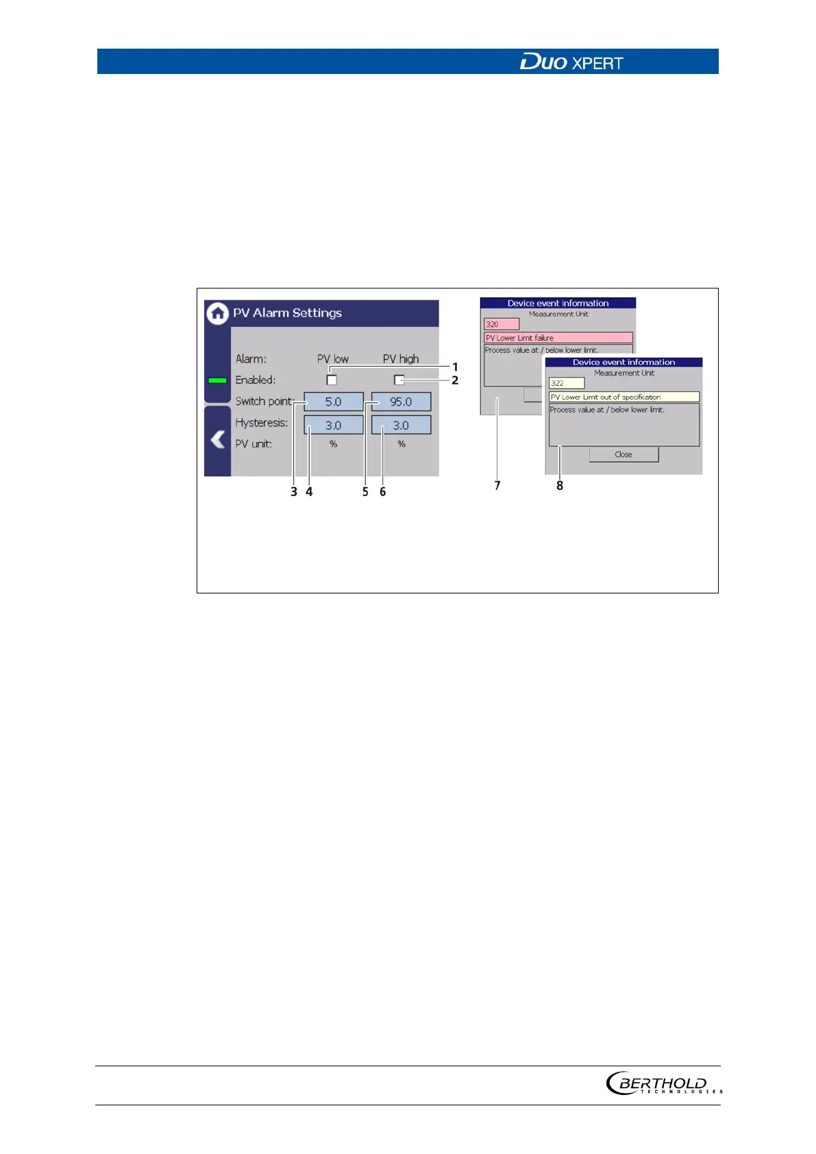
PV Alarm Settings
Device settings | Setup | Alarms | PV alarm settings
You can set the values for the level alarms (max. and min.) and the hysteresis of
these in the submenu ″PV Alarm Settings″.
When exceeding or falling below the switching point, an event message appears
in the status display. If a digital output "min. level Alarm" or "max. level Alarm" is
assigned under the function (Fig. 126, item 6), the relay switches.
Hysteresis is defined as the tolerance range of the alarm trigger which occurs at a
predefined threshold of the process range.
Selection box “PV low”
Selection box “PV high”
Input box “Switch point Low”
Input box “Hysteresis Low”
Input box “Switch point High”
Input box “Hysteresis Low”
Event message “Failure”
Event message “Out of specifica-
tion”
127 PV Alarm Settings
Example: Tolerance range = 5%, Process range = 20% and 85%
In the event of a rising process range, the max. alarm is triggered when a process
range of 85% is exceeded. When the process range falls again, then the alarm does
not switch off again until the process range falls below 85% - 5% = 80%.
In the event of a falling process range, the min. alarm is triggered when a process
range falls below 20%. When the process range rises again, then the alarm does
not switch off again until the process range rises above 20% + 5% = 25%.
 Loading...