BestCode Next Series 8 Technical Manual October 2022 Page 289 of 290
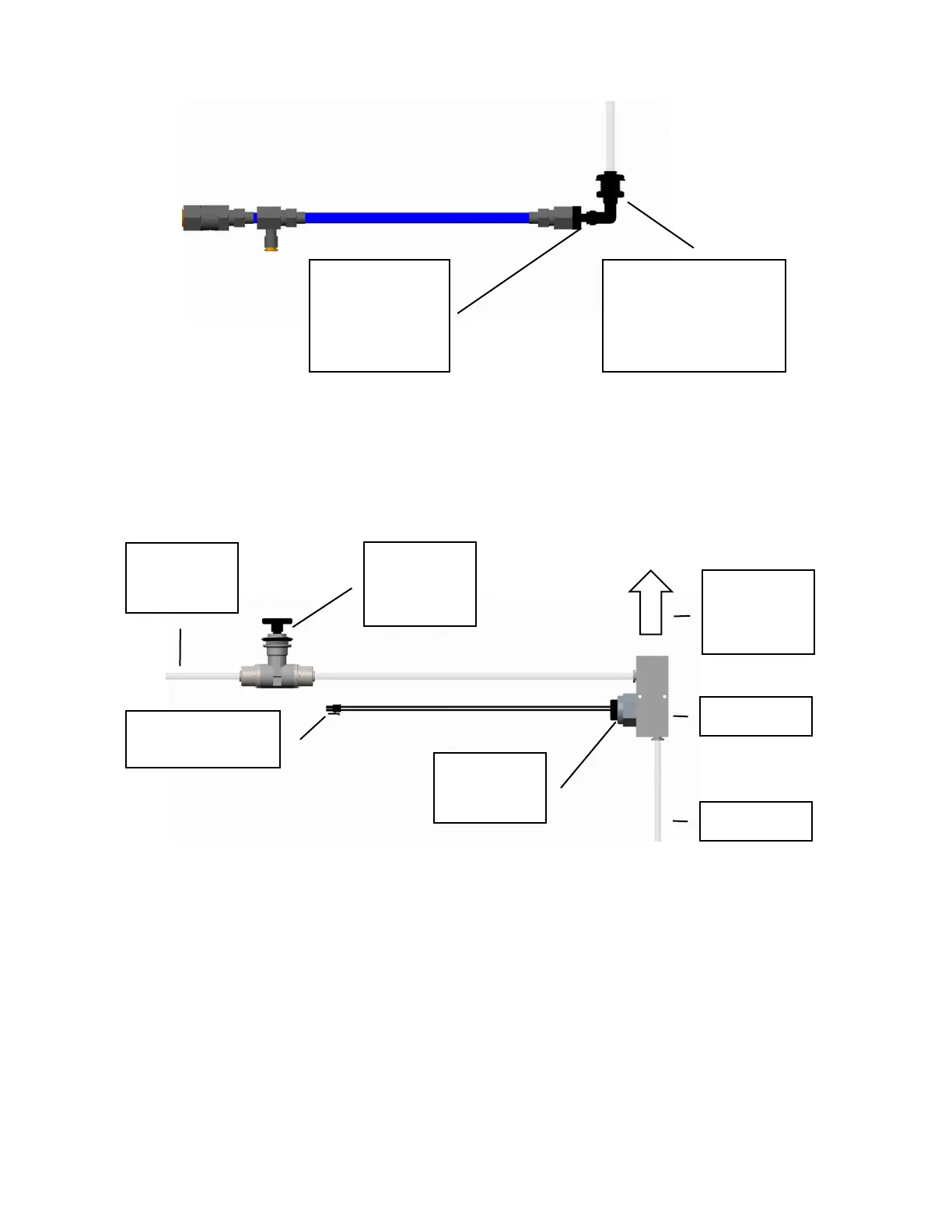
Diagram 3: Cabinet Air Entry
The output from the Micro-membrane filter is a ¼” quick disconnect stem that plugs into the 90° ¼” Quick Connect
bulkhead fitting. The bulkhead fitting is internally sealed with a O-Ring nut and connects to a ¼” OD Teflon tube that
supplies the clean air into the Cabinet Air Manifold.
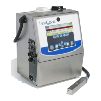
Diagram 4: Cabinet Air Distribution Manifold
Air is supplied from the Air Dryer and enters the Air Manifold. The pressure is measured here using a simple NC
Pressure sensor coil to ensure enough air flow is provided to the Cabinet to adequately cool and keep the system
pressurized. A hole is drilled in the opposite end of the manifold to provide air input. The only air flow control system
for the cabinet is the original air input pressure to the dryer.
The Air Pressure Sensor must be connected to J26 (Air Cooler) on the main board. If the Air Pressure Sensor is not
connected to the board, the closed state will not be achieved, and the system will not complete the power on function.
The Air Manifold can be accessed by removing the 4 M3 Socket head screws inside the cabinet filter door. Per the
included warning, this door must not be opened while the system is powered on.