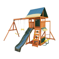
Ground SL Side 1 x 6 x 41½"
(E30)
1X
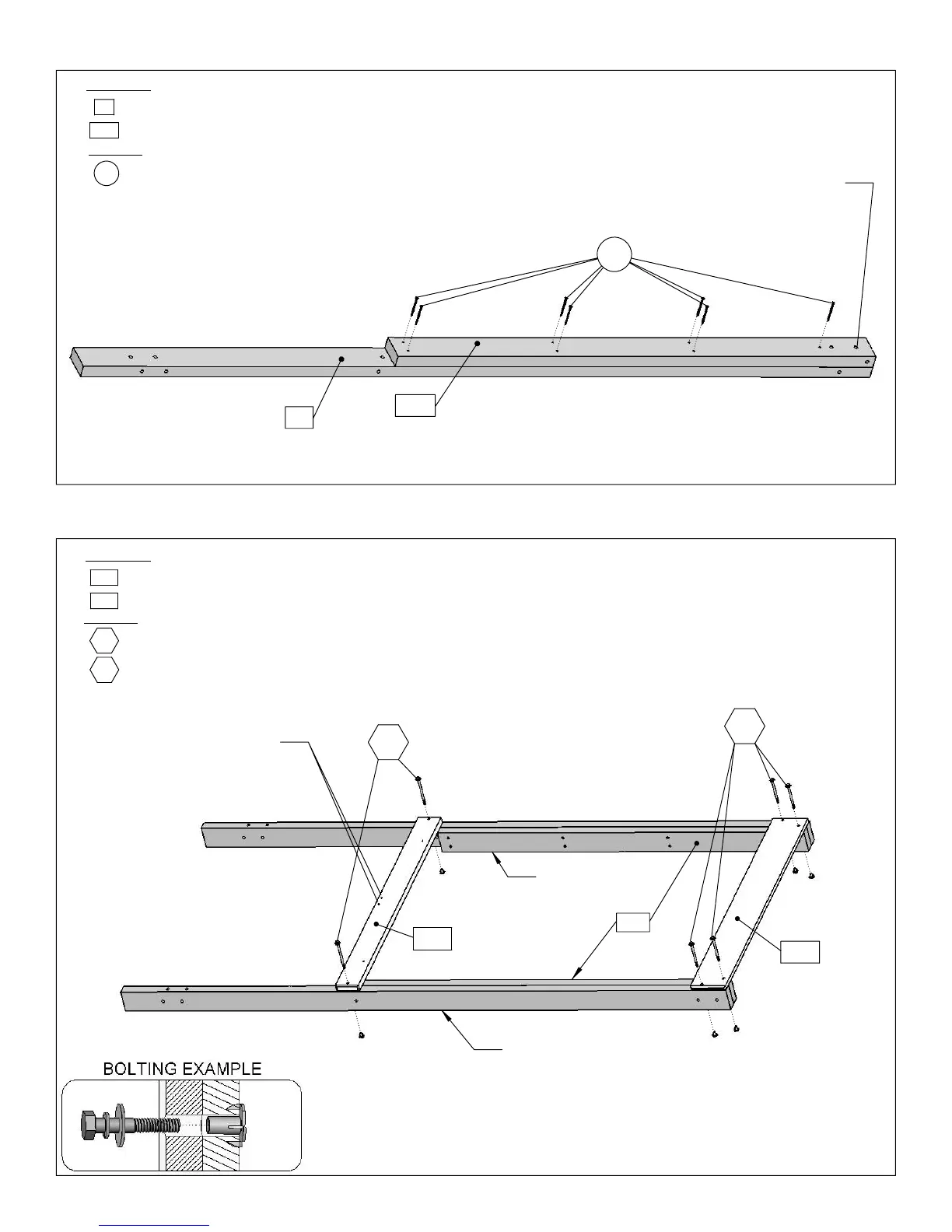
Post 2 x 4 x 92½"
1X
B
H5
SL Floor 5/4 x 4 x 41½"
Lower Post using 2
Hardware
Hex Bolt 1/4 x 4"
Wood Parts
SL Floor are oriented towards the top of the assembly.
Wood Screw #8 x 2½"
(B13)
SL Floor to the Post Assemblies right above the
wood screws.
#8 x 2½” Post using 7
2X
(S3)
in
(E30)
E30
4X
(H5)
E13
1/4 x 4½” hex bolts (with flat
B13
S3
C4
washer, lock washer and t-nut). Note that the two middle holes
4X
Wood Parts
28X
Lower Post 2 x 4 x 56"4X
: Repeat Step A 3 more times to have 4 Post Assemblies.
: Attach
(C4)
Hardware
A
: Attach
(E13)
Ground SL Side to bottom of 2 Post Assemblies
using 4
(H4)
1/4 x 4” hex bolts (with flat washer, lock washer and
t-nut). Make sure the
(B13)
Lower Posts are on the inside of the
assembly.
B
A
: Attach
(B13)
Lower Post to
H4
Hex Bolt 1/4 x 4½"
S3
C4
B13
Use 5/16 Bolt to line up holes
E30
Holes must be
oriented as shown
E13
Post Assembly
H5
Post Assembly
H4
B13
STEP 3 Post Assembly
STEP 4 Slide Wall Assembly
19