S2
3 per
to arch cutout)
D5
Note:
Post Assembly
E15
and center
(top row only)
D5
(bottom row
only)
D5
2 per
S2
S1
C13
4 per
B6
's are flush
(D5)
E39
B6
C9
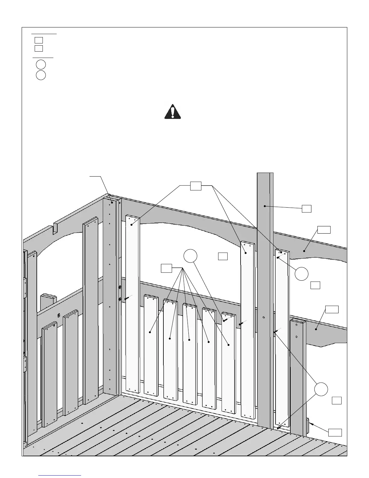
STEP 16 Attach Back Wall Boards
CE Window Brace 1 x 4 x 41¾"
S2
Cedar Wall 1 x 4 x 23½"B6
3X
Wood Parts
6X
Hardware
Wood Screw #8 x 1ǩ"
D5
5X
S1
Wood Screw #8 x 1½"29X
#8 x 1½” wood screws per board. Make sure boards are evenly
spaced, gaps not exceeding 1½".
A
: On either side of
(C9)
Roof Upright and beside Post
Assembly attach 3
(D5)
CE Window Brace to
(E15)
Top Back
using 2
(S1)
#8 x 1ǩ” wood screws per board; to
(E39)
Middle
back using 1
(S2)
#8 x 1½” per board; and to
(C13)
Lower Back
using 2
(S2)
#8 x 1½” wood screws per board.
B
: Between 2
(D5)
CE Window Braces attach 5
(B6)
Cedar
Wall to
(E39)
Middle Back and
(C13)
Lower Back using 4
(S2)
Warning.
Space evenly. Do not exceed 1½"
31