KBW (E6) 11/2016 page 2/147
Content
1. SAFETY .................................................................................................................. 6
1.1 Legal considerations ........................................................................................................................... 6
1.2 Structure of the safety instructions ...................................................................................................... 6
1.2.1 Signal word panel ...................................................................................................................... 6
1.2.2 Safety alert symbol .................................................................................................................... 7
1.2.3 Pictograms ................................................................................................................................. 7
1.2.4 Word message panel structure ................................................................................................. 8
1.3 Localization / position of safety labels on the chamber ....................................................................... 8
1.4 Type plate ............................................................................................................................................ 9
1.5 General safety instructions on installing and operating the chambers .............................................. 10
1.6 Intended use ...................................................................................................................................... 12
1.7 Operating instructions ....................................................................................................................... 12
1.8 Measures to prevent accidents ......................................................................................................... 13
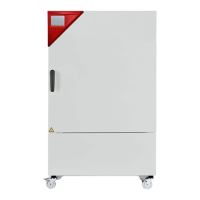
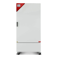
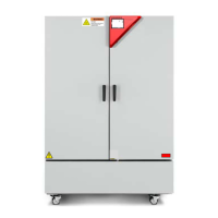
2. CHAMBER DESCRIPTION AND OVERVIEW ..................................................... 14
2.1 Chamber description ......................................................................................................................... 14
2.2 Chamber overview ............................................................................................................................ 15
2.3 Instrument panel................................................................................................................................ 15
2.4 Lateral control panels ........................................................................................................................ 16
3. COMPLETENESS OF DELIVERY, TRANSPORTATION, STORAGE, AND
INSTALLATION .................................................................................................... 17
3.1 Unpacking, and checking equipment and completeness of delivery................................................. 17
3.2 Guidelines for safe lifting and transportation ..................................................................................... 18
3.3 Storage .............................................................................................................................................. 18
3.4 Location of installation and ambient conditions ................................................................................. 18
4. INSTALLATION AND CONNECTIONS ................................................................ 20
4.1 Spacer for wall distance .................................................................................................................... 20
4.2 Mounting the flexible tilt protection kit (KBW 400) ............................................................................. 21
4.3 Installation and connection of the light cassettes .............................................................................. 22
4.4 Electrical connection ......................................................................................................................... 23
5. FUNCTIONAL OVERVIEW OF THE MB2 CHAMBER CONTROLLER ............... 24
5.1 Operating functions in normal display ............................................................................................... 25
5.2 Display views: Normal display, program display, chart-recorder display ........................................... 26
5.3 Controller icons overview .................................................................................................................. 27
5.4 Operating modes ............................................................................................................................... 29
5.5 Controller menu structure .................................................................................................................. 30
5.5.1 Main menu ............................................................................................................................... 31
5.5.2 “Settings” submenu ................................................................................................................. 32
5.5.3 “Service” submenu .................................................................................................................. 32
5.6 Principle of controller entries ............................................................................................................. 33
5.7 Performance during and after power failures .................................................................................... 33
5.8 Performance when opening the door ................................................................................................ 34
6. START UP ............................................................................................................ 34
6.1 Turning on the chamber .................................................................................................................... 34
6.2 Controller settings upon start up ....................................................................................................... 35
7. SET-POINT ENTRY IN “FIXED VALUE” OPERATING MODE ........................... 36
7.1 Set-point entry through the “Setpoints” menu ................................................................................... 37
7.2 Direct setpoint entry via Normal display ............................................................................................ 38
7.3 Automatic correction of the actual value when turning on or off the illumination .............................. 38
7.4 Light commutation and special controller functions via operation lines ............................................ 39