CB / CB-UL, CBF / CBF-UL (E7) 01/2022 Page 27/199
(N) Pump (CBF / CBF-UL)
(O) Water connection for silicone tube (CBF / CBF-UL)
(P) Opening for freshwater bag (CBF / CBF-UL)
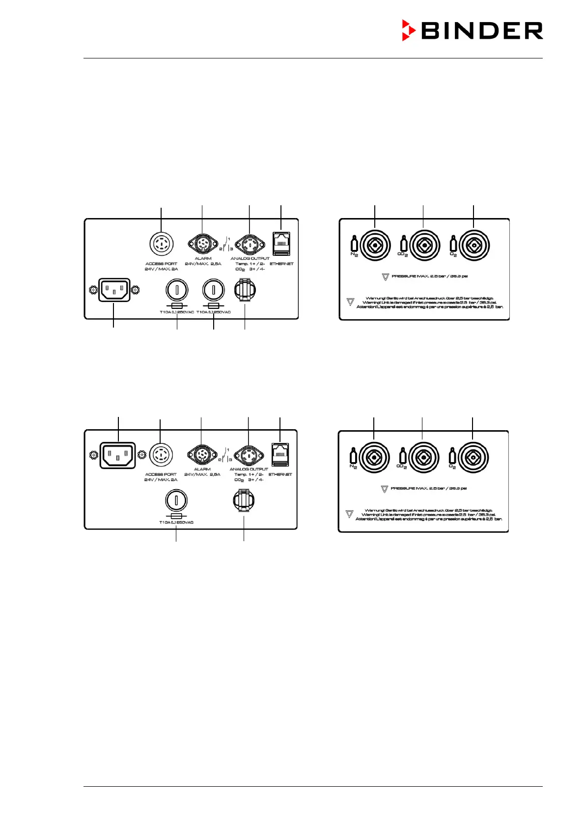
2.3 Control panel on the rear of the chamber
(2) (3) (4) (5) (9) (10) (11)
(1b) (6b) (7) (8)
Figure 6: Rear control panel CB with O
2
control and options
(1b) (2) (3) (4) (5) (9) (10) (11)
(6a) (8)
Figure 7: Rear control panel CB-UL with O
2
control and options
(1a) Socket for IEC connector plug / power cable 100-120 V AC
(1b) Socket for IEC connector plug / power cable 230 V AC
(2) External socket for extra-low voltage supply (option for chamber size 170 / 220, chap. 18.7)
(3) DIN-socket for zero-voltage relay alarm outputs
(4) DIN socket for analog outputs 4-20 mA (option, chap. 18.5)
(5) Ethernet interface for computer communication
(6a) Miniature fuse T12,5 A (L) 250 V AV for 100-120 V chamber
(6b) Miniature fuse T10 A (L) 250 V AC for 200-230 V chamber
(7) Miniature fuse T10 A (L) 250 V AC for 200-230 V chamber