18
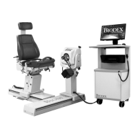
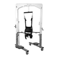
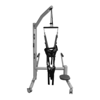
Figure 2.5. Attaching the Seatback Brace to the System 4 Trolley Mount Clevis.
4. Loosen the Seat Back Brace locking
knob. Extend the lower part of the
brace and insert the rod-end swivel into
the trolley mount clevis. Insert the
clevis pin.
5. Position the patient per protocol; lock
the Seat Back Brace locking knob to
secure. Be sure to loosen the seat
locking knob when adjusting the height
of the seat or the position of the seat
back.
6. To rotate the seat to the opposite 0-
degree position, disconnect the lower
end of the back only. Repeat steps four
and five.
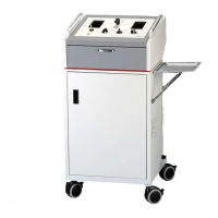
The Controller
(Located at the bottom, rear, of Computer Data Station)
Main Power Switch: Controls main power supply to controller, computer and dynamometer.
Contains a circuit breaker to protect against extreme power surges. Breaker is reset by turning
the Power Switch OFF (0) and ON (l).
NOTE: At the end of each day, leave both the Green Dynamometer and Power switches ON.
Then turn OFF the Main Power Switch. This will help prevent possible damage during storms,
or electrical surges.
Dynamometer Power Switch: This switch controls power to the dynamometer. In the ON
position, power to the dynamometer is enabled. In the OFF position, the dynamometer is on
Standby.
Computer Power Switch: Controls power to the computer and peripherals (including printer and
monitor). In the ON position, power to computer, monitor and printer are ON. In the OFF position,
power to the computer, monitor and printer are OFF.
NOTE: Be sure to properly exit and close down the Software application and Windows
Programs before turning off the computer.
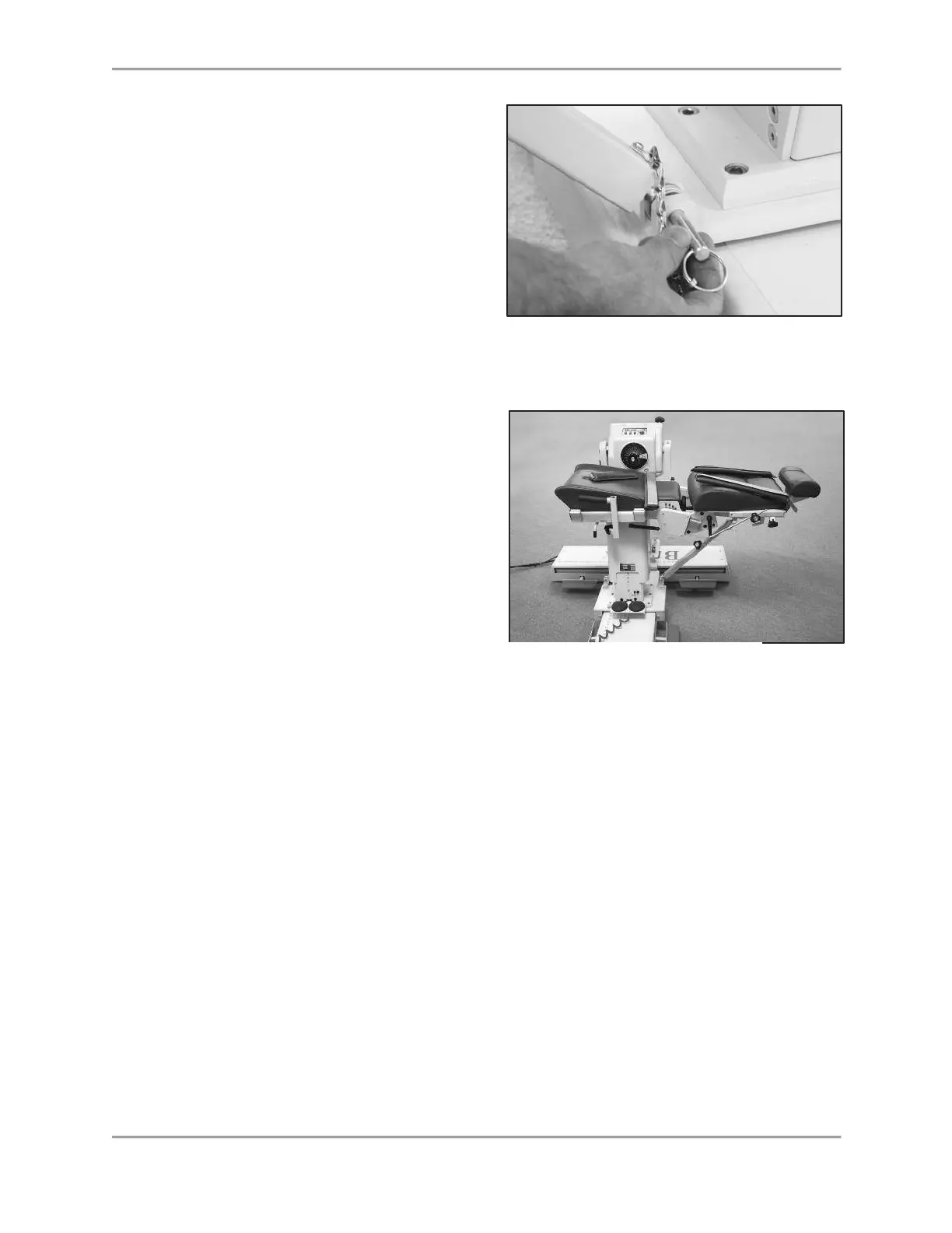
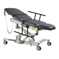
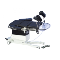
Figure 2.6. Seat Backbrace Installed and Ready for Use.