4-3-6 Thermal Pinter Circuit
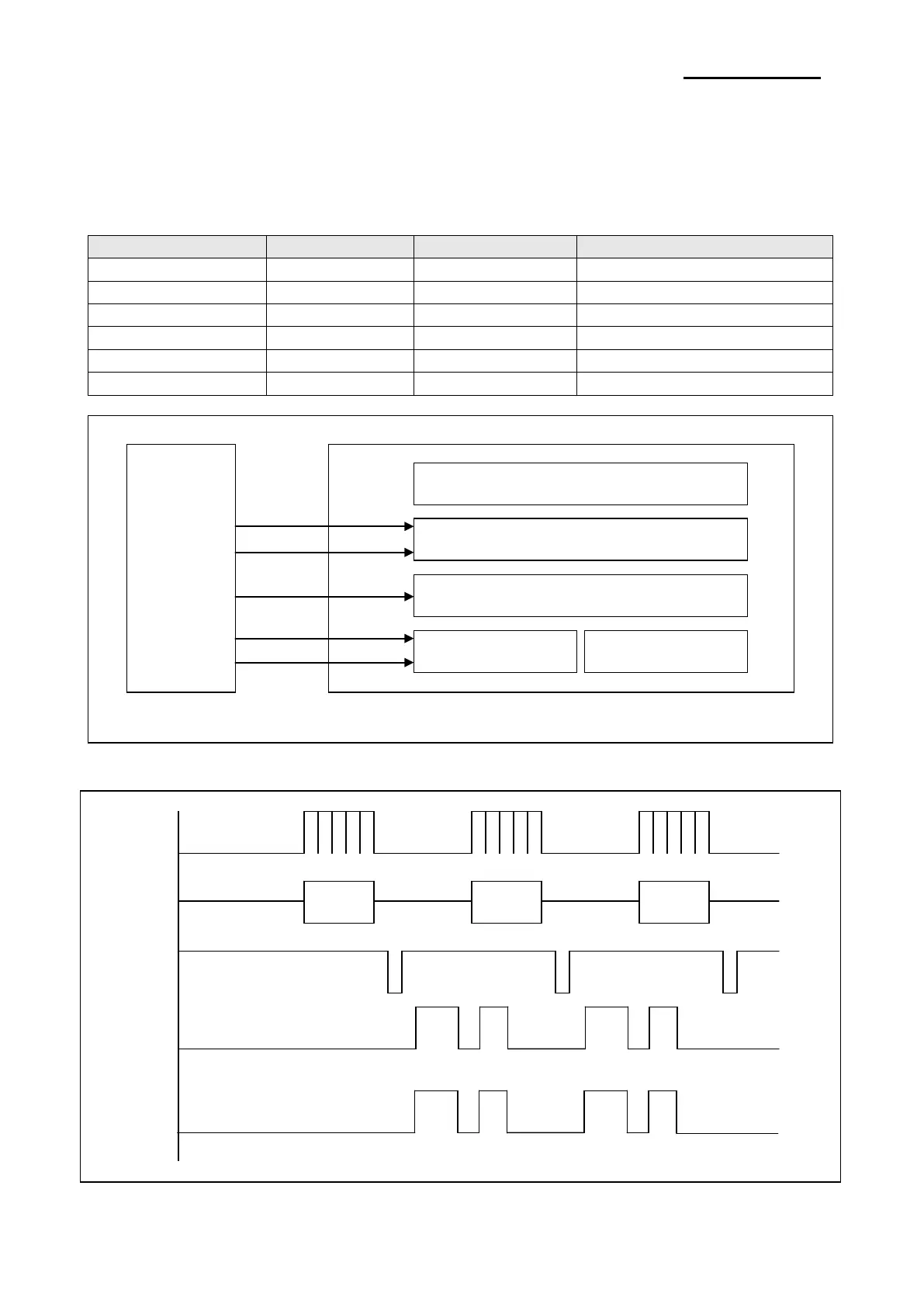
First, the CPU sends a serial clock and serial data 832bits (104bytes) to the shift register of the TPH. Second,
the CPU send a Latch signal to the TPH. Then the Data of both shift register#1 and #2 are moved to the
Latch register. After that the CPU sends a strobe signal to the TPH. Then the TPH outputs the serial data.
Each strobe signal controls the each dot of TPH.
Table 4-1 Printer Head Strobe Processing
STB3 321 ~ 448 128 TPH_STB1
CPU
Printer Line
Strobe Circuit
Latch Register
Shift Register #1 Shift Register #2
TPH
Figure 4-6 Thermal Printer Block Diagram
Figure 4-7 Thermal Printer Timing Waveform
2
bits
bits
bits
832 bits
832 bits
Ver. 1.01
- 35 -