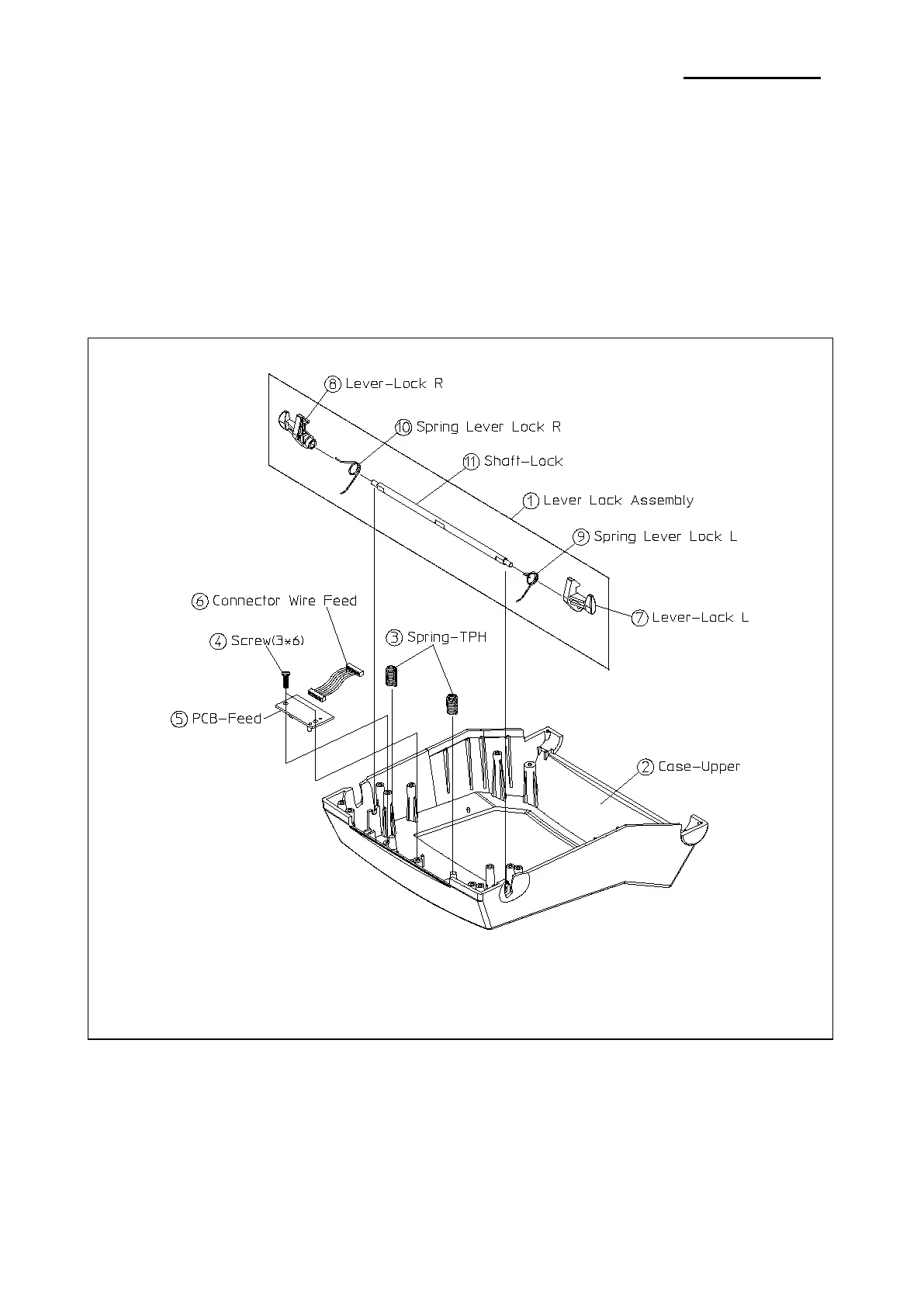
5-3-4 Lever Lock Block
Figure 5-12 Disassembly Case Upper #4
1. Lift the Lever-Lock Assembly
①
②
2. Separate the two Spring-TPH③ from the Case-Upper②.
3. Remove the two Screws④.
4. Separate the PCB-Feed⑤ from the Case-Upper②.
5. Separate the Connector Wire Feed⑥ from the PCB-Feed⑤.
* Disassembly Lever Lock Assembly
1. Separate the Lever-Lock L⑦ / R⑧ from the Shaft-Lock⑪.
2. Separate the Spring Lever Lock L⑨ / R⑩ from the Lever-Lock L⑦ / R⑧.
Ver. 1.01
- 47 -