24
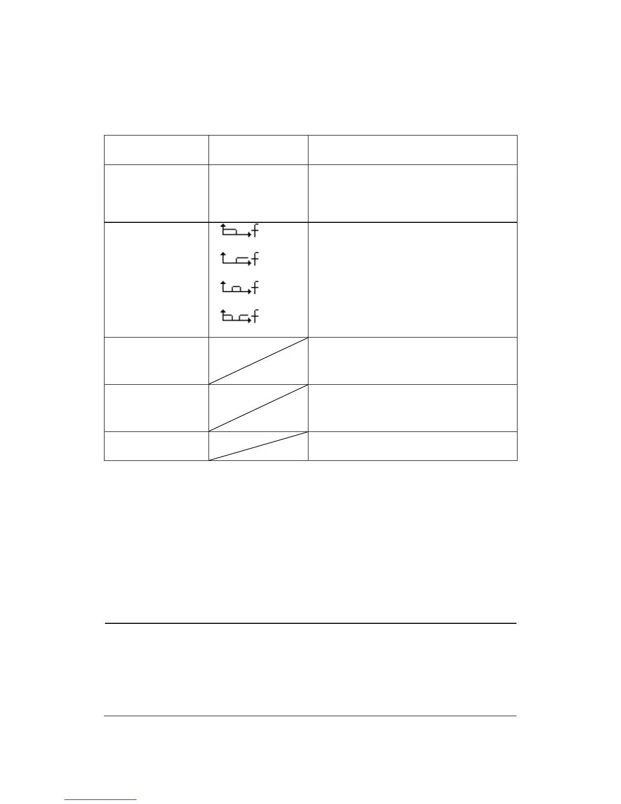
Table 3.6 – Digital Filter Menu
Turn on the digital filter.
Turn off the digital filter.
Setup as LPF (Low Pass Filter).
Setup as HPF (High Pass Filter).
Setup as BPF (Band Pass Filter).
Setup as BRF (Band Reject Filter).
Turn the “Universal” knob to set
upper limit.
Turn the “Universal” knob to set
lower limit.
Return to the second page menu.
• “GND” Coupling: Use GND coupling to display a zero-volt
waveform. Internally, the channel input is connected to a zero-
volt reference level.
• Fine Resolution: The vertical scale readout displays the actual
Volts/Div setting while in the fine resolution setting. Changing the
setting to coarse does not change the vertical scale until the
VOLTS/DIV control is adjusted.
NOTE:
The oscilloscope’s vertical response rolls off slowly above its
specified bandwidth. Therefore, the FFT spectrum can show valid
frequency information higher than the oscilloscope’s bandwidth.
However, the magnitude information near or above the