27
CHAPTER 1: HEADLINE
1. 8 7 7. 8 7 7. 2 26 9 BLACKBOX.COM
NEED HELP?
LEAVE THE TECH TO US
LIVE 24/7
TECHNICAL
SUPPORT
1.877.87 7.2269
CHAPTER 2: OVERVIEW
2.3.3 LES1700 SERIES
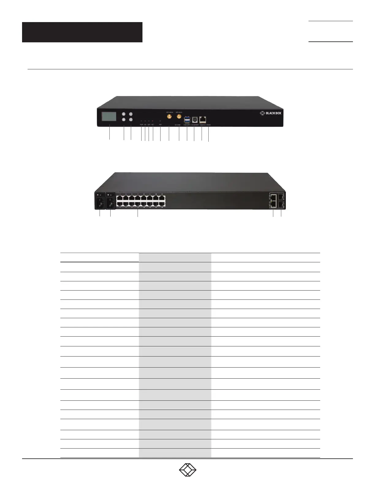
Figures 2-5 and 2-6 show the front and back panels of the LES1716A. Table 2-5 describes its components.
1 2 3 4 5 6 7 8 9 10 11 12 13 14
FIGURE 2-5. LES1716A FRONT PANEL
15 16 17 18 19
FIGURE 2-6. LES1716A BACK PANEL
TABLE 2-5. LES1716A CONSOLE SERVER COMPONENTS
NUMBER IN FIGURE 2-5 OR 2-6 COMPONENT DESCRIPTION
1 LCD screen LCD configuration
2 UP button Scroll up in the menu
2 DOWN button Scroll down in the menu
3 OK button Confirm selection
3 BACK button Go back to previous selection
4 PWR LED Lights when power is on
5 H/B LED Heartbeat LED, lights when firmware is running
6 Serial LED Active serial communication
7 NET LED Active network communication
8 WiFi LED Lights when WiFi is active
9, 10 WiFi antenna connectors Connects to the main or auxiliary WiFi antenna
10 SD card slot Expand storage
11 (2) USB ports Link to USB consoles
12 V.92 modem port Port for analog dialup
13 RJ-45 console port Attaches to serial console
14 Erase button Push to erase settings and configuration
15, 16 (2) 3-prong power receptacles Link to power supplies
16 (2) I/O switches Turns power ON or OFF
17 (16) RJ-45 ports Link to serial devices
18, 19 (2) RJ-45/SFP ports Link to Ethernet network ports NET1 and NET2



 To Next Page