Fa
THE
AUTOMATIC TRANSMISSION
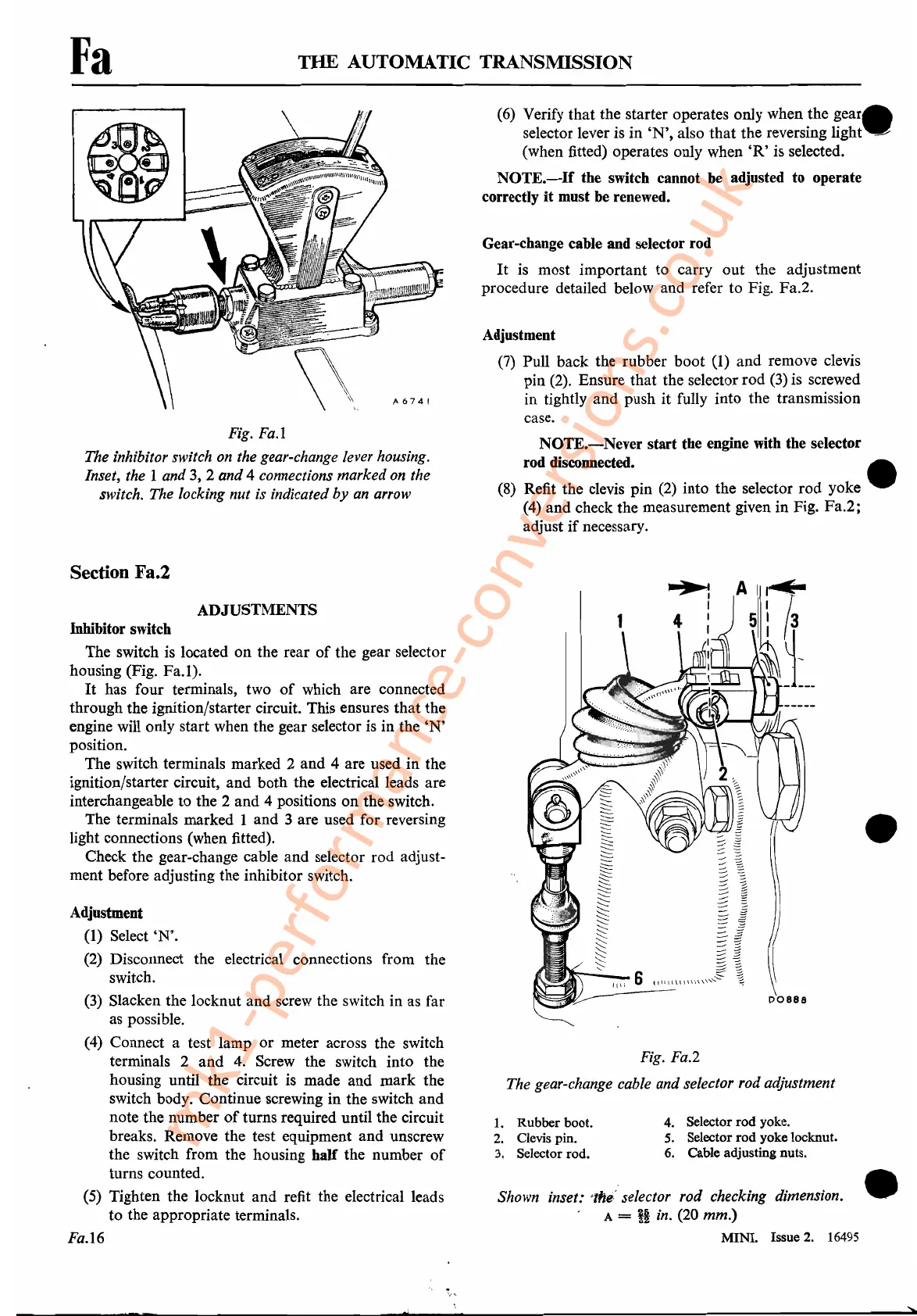
Fig.
Fa.1
The inhibitor switch on the gear-change lever housing.
Inset, the
I and 3, 2 and 4 connections marked on the
switch. The locking nut is indicated
by
an arrow
Section Fa.2
(6) Verify that the starter operates only when the
gear.
selector lever is in
'N',
also that the reversing light
..
~
(when fitted) operates only when
'R'
is selected.
NOTE.-If
the switch cannot be adjusted
to
operate
correctly
it
must be renewed.
Gear-change cable and selector rod
It
is
most important to carry out the adjustment
procedure detailed below and refer to Fig. Fa.2.
Adjustment
(7)
Pull back the rubber boot (1) and remove clevis
pin
(2).
Ensure that the selector rod
(3)
is screwed
in tightly and push it fully into the transmission
case.
NOTE.-Never
start
the engine with the selector
rod disconnected. •
(8)
Refit the clevis pin
(2)
into the selector rod yoke
(4)
and check the measurement given in Fig. Fa.2;
adjust
if
necessary.
Shown inset: 'tfte' selector rod checking dimension.
A =
it
in. (20 mm.)
MINI.
Issue
2.
16495
Fig. Fa.2
The gear-change cable and selector rod adjustment
ADJUSTMENTS
Inhibitor switch
The switch is located on the rear
of
the gear selector
housing (Fig. Fa.l).
It
has four terminals, two
of
which are connected
through the ignition/starter circuit. This ensures that the
engine will only start when the gear selector
is
in the
'N'
position.
The switch terminals marked 2 and 4 are used in the
ignition/starter circuit, and both the electrical leads are
interchangeable to the 2 and 4 positions
on
the switch.
The terminals marked 1 and 3 are used for reversing
light connections (when fitted).
Check the gear-change cable and selector rod adjust-
ment before adjusting the inhibitor switch.
Adjustment
(I) Select
'N'.
(2)
Disconnect the electrical connections from the
switch.
(3)
Slacken the locknut and screw the switch in as far
as possible.
(4)
Connect a test lamp or meter across the switch
terminals 2 and
4.
Screw the switch into the
housing until the circuit is made and mark the
switch body. Continue screwing in the switch and
note the number
of
turns required until the circuit
breaks. Remove the test equipment and unscrew
the switch from the housing
half
the number
of
turns counted.
(5) Tighten the locknut and refit the electrical leads
to the appropriate terminals.
Fa.16
1.
Rubber boot.
2.
Clevis pin.
3. Selector rod.
4. Selector
rod
yoke.
5. Selector
rod
yoke locknut.
6. Cable adjusting nuts.
•
•
mk1-performance-conversions.co.uk
 Loading...


