THE
AUTOMATIC TRANSMISSION
• Testing adjustment
(12)
Apply the hand and foot brakes, and ensure that
the starter operates only in the
'N'
position;
if
this
is
notcorrect, adjust the inhibitor switch as detailed
in items (1) to (6).
(13) Start the engine, and move the gear lever to the
'R'
position and check that reverse
is
engaged.
Slowly move the lever back towards the
'N'
position, checking that the gear
is
disengaged just
before
or
as soon as the lever drops into the
'N'
position on the quadrant. Repeat this procedure
in the first gear '1' position. Re-adjust the outer
cable slightly
if
necessary to obtain the above con-
ditions.
Fa
Governor control rod adjustment .
...
. .':
(16)
Run the engine to its normal working
temperaJl~'
(17)
Disconnect the governor control rod
at
the carbu-
retter.
(18)
With the carburetter correctly tuned, adjust the
throttle adjusting screw to give a tachometer read-
ing
of
650
r.p.m.
at
tickover.
(19)
Insert a i in. (6,4 mm.) diameter rod through the
hole in the governor control
rod
bell-crank lever
and into the hole in the transmission case (Fig.
Fa.3).
(20) Slacken the locknut
(3)
(Fig. Fa.3) and adjust the
length
of
the rod to suit the carburetter linkage in
the tick-over position.
(21)
Reconnect the governor control rod to the carbu-
retter. Tighten the ball joint locknut and remove
the checking rod from the bell-crank lever.
(14)
Ensure that all adjustment/locking nuts are tight
and the
c1evis
pins are secured. Pack the rubber
boots with Duckham's Lammol grease. Refit the
boots and the weather protection shield (if fitted).
(15)
Carry out a road test, checking the operation in
each gear lever position.
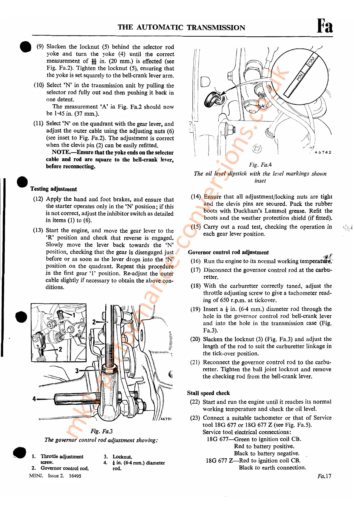
Fig.
FaA
The oil level dipstick with the level markings shown
inset
Fa.I7
Stall speed check
(22)
Start and run the engine until it reaches its normal
working temperature and check the oil level.
(23)
Connect a suitable tachometer
or
that
of
Service
tooI18G
677
or
l8G
677
Z (see Fig. Fa.5).
Service tool electrical connections:
18G
677-Green
to ignition 'coil CB.
Red to battery positive.
Black to battery negative.
18G
677
Z-Red
to ignition coil CB.
Black
to
earth connection.
3.
Locknut.
4.
*in. (6'4
mm.)
diameter
rod.
(9)
Slacken the locknut
(5)
behind the selector rod
yoke and turn the yoke
(4)
until the correct
measurement
of
H in.
(20
mm.)
is
effected (see
Fig. Fa.2). Tighten the locknut (5), ensuring that
the yoke is set squarely to the bell-crank lever arm.
(10) Select
'N'
in the transmission unit by pulling the
selector rod fully out and then pushing it back in
one detent.
The measurement
'A'
in Fig. Fa.2 should now
be
1·45
in.
(37
mm.).
(11)
Select
'N'
on the quadrant with the gear lever, and
adjust the outer cable using the adjusting nuts
(6)
(see inset to Fig. Fa.2). The adjustment is correct
when the clevis pin
(2)
can be easily refitted.
NOTE.-Ensure
that
the yoke ends on the selector
cable and rod are square
to
the bell-crank lever,
before reconnecting.
1.
Throttle adjustment
screw.
2. Govemorcontrol rod.
MINI.
Issue 2. 16495
Fig. Fa.3
The governor control rod adjustment showing:
•
4-_==~iII
\
~:.:
~
~
.......
, U
,.
•••
"".,'
..
I1II1I1OII
1
"'#
~.
•
•
mk1-performance-conversions.co.uk