THE
AUTOMATIC TRANSMISSION
•
•
•
•
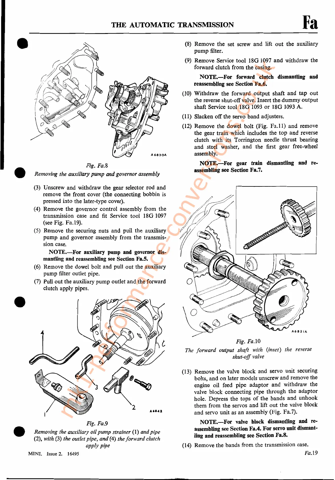
Fig. Fa.8
Removing the auxiliary pump and governor assembly
(3)
Unscrew and withdraw the gear selector rod and
remove the front cover (the connecting bobbin
is
pressed into the later-type cover).
(4)
Remove the governor control assembly from the
transmission case and
fit
Service tool
180
1097
(see Fig. Fa.19).
(5)
Remove the securing nuts and pull the auxiliary
pump and governor assembly from the transmis-
sion case.
NOTE.-For
auxiliary
pump
and governor dis-
mantling and reassembling see Section Fa.5.
(6)
Remove the dowel bolt and pull out the auxiliary
pump filter outlet pipe.
(7)
Pull out the auxiliary pump outlet and the forward
clutch apply pipes.
Fig. Fa.9
Removing the auxiliary oil pump strainer
(1) andpipe
(2), with
(3) the outlet pipe, and (4) the forward clutch
apply pipe
MINI.
Issue 2. 16495
Fa
(8)
Remove the set screw and lift out the auxiliary
pump filter.
(9)
Remove Service tool
180
1097
and withdraw the
forward clutch from the casing.
NOTE.-For
forward clutch dismantling and
reassembling see Section Fa.6.
(10)
Withdraw the forward output shaft and tap out
the reverse shut-offvalve. Insert the dummy output
shaft Service tool
180
1093
or
180
1093
A.
(11)
Slacken off the servo band adjusters.
(12)
Remove the dowel bolt (Fig.
Fa.ll)
and remove
the gear train which includes the top and reverse
clutch with its Torrington needle thrust bearing
and steel washer, and the first gear free-wheel
assembly.
NOTE.-For
gear train dismantling and re-
assembling see Section Fa.7.
Fig. Fa.lO
The forward output shaft with (inset) the reverse
shut-off valve
(13)
Remove the valve block and servo unit securing
bolts, and on later models unscrew and remove the
engine oil feed pipe adaptor and withdraw the
valve block connecting pipe through the adaptor
hole. Depress the tops
of
the bands and unhook
them from the servos and lift out the valve block
and servo unit as an assembly (Fig. Fa.7).
NOTE.-For
valve
block dismantling and re-
assembling see Section Fa.4. For servo unit dismant-
ling and reassembling see Section Fa.8.
(14)
Remove the bands from the transmission case.
Fa.l9
mk1-performance-conversions.co.uk