Fa
THE
AUTOMATIC TRANSMISSION
•
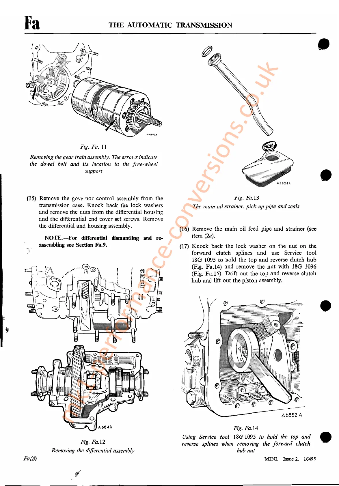
Fig.
Fa.l4
Using Service tool
18G
1095
to hold the top
and
•
reverse splines when removing the forward clutch
hub nut
Fig.
Fa.
II
Removing the gear train assembly. The arrows indicate
the dowel bolt and its location
in
the free-wheel
support
(15) Remove the governor control assembly from the
transmission case. Knock back the lock washers
and remove the nuts from the differential housing
and the differential end cover set screws. Remove
the differential and housing assembly.
NOTE.-For
differential dismantling and re-
assembling see Section Fa.9.
Fig. Fa.12
Removing the differential assembly
Fig. Fa.13
The main oil strainer, pick-up pipe and seals
(16)
Remove the main oil feed pipe and strainer (see
item
(2a).
(17) Knock back the lock washer on the
nut
on the
forward clutch splines and use Service tool
18G
1095
to hold the top and reverse clutch hub
(Fig. Fa.14) and remove the
nut
with 18G
1096
(Fig. Fa.15). Drift out the top and reverse clutch
hub and lift out the piston assembly.
•
•
Fa.20
MINI. Issue
2.
16495
mk1-performance-conversions.co.uk