Fa
THE AUTOMATIC TRANSMISSION
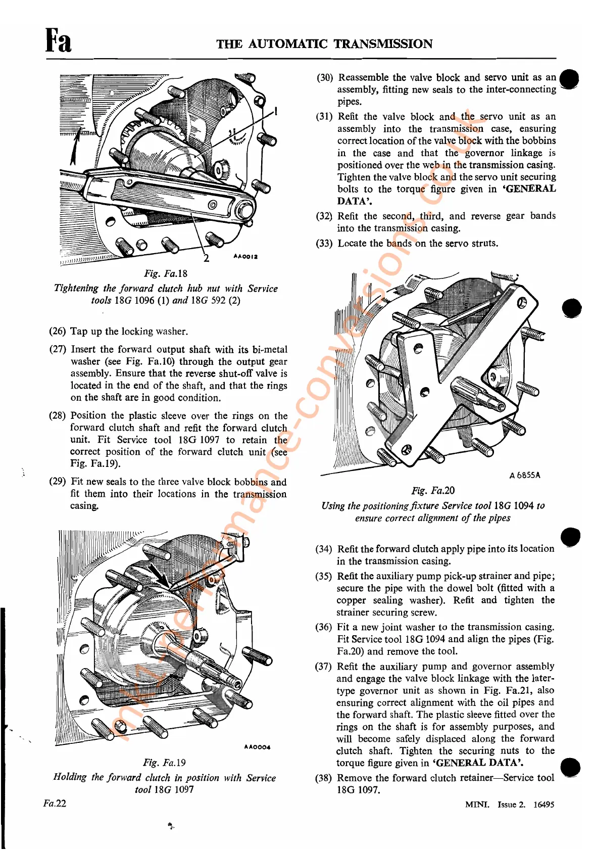
Fig. Fa.18
Tightening the forward clutch hub nut with Service
tools
18G
1096
(1) and
18G
592
(2)
(26)
Tap up the locking washer.
(27)
Insert the forward output shaft with its bi-metal
washer (see Fig. Fa.l0) through the output gear
assembly. Ensure that the reverse shut-off valve
is
located in the end
of
the shaft, and that the rings
on the shaft are in good condition.
(28)
Position the plastic sleeve over the rings on the
forward clutch shaft and refit the forward clutch
unit. Fit Service tool
180
1097
to retain the
correct position
of
the forward clutch unit (see
Fig. Fa.19).
(29)
Fit new seals to the three valve block bobbins and
fit them into their locations in the transmission
casing.
Fig. Fa.19
Holding the forward clutch in position with Service
tool18G 1097
Fa.22
(30)
Reassemble the valve block and servo unit as an •
assembly, fitting new seals to the inter-connecting'
pipes.
(31)
Refit the valve block and the servo unit as an
assembly into the transmission case, ensuring
correct location
of
the valve block with the bobbins
in the case and that the governor linkage
is
positioned over the web in the transmission casing.
Tighten the valve block and the servo unit securing
bolts to the torque figure given in 'GENERAL
DATA'.
(32)
Refit the second, third, and reverse gear bands
into the transmission casing.
(33)
Locate the bands on the servo struts.
•
Fig. Fa.20
Using the positioningfixture Service tool18G
1094
to
ensure correct alignment
of
the pipes
(34) Refit the forward clutch apply pipe intoits location •
in the transmission casing.
(35)
Refit the auxiliary pump pick-up strainer and pipe;
secure the pipe with the dowel bolt (fitted with a
copper sealing washer). Refit and tighten the
strainer securing screw.
(36)
Fit a new joint washer to the transmission casing.
Fit Service tool
180
1094
and align the pipes (Fig.
Fa.20) and remove the tool.
(37)
Refit the auxiliary pump and governor assembly
and engage the valve block linkage with the later-
type governor unit as shown in Fig. Fa.21, also
ensuring correct alignment with the oil pipes and
the forward shaft. The plastic sleeve fitted over the
rings on the shaft is for assembly purposes, and
will become safely displaced along the forward
clutch shaft. Tighten the securing nuts to the
torque figure given in 'GENERAL DATA'. •
(38)
Remove the forward clutch retainer-Service tool . .
180
1097.
MINI. Issue
2.
16495
mk1-performance-conversions.co.uk



 To Next Page