THE
AUTOMATIC TRANSl\tIISSION
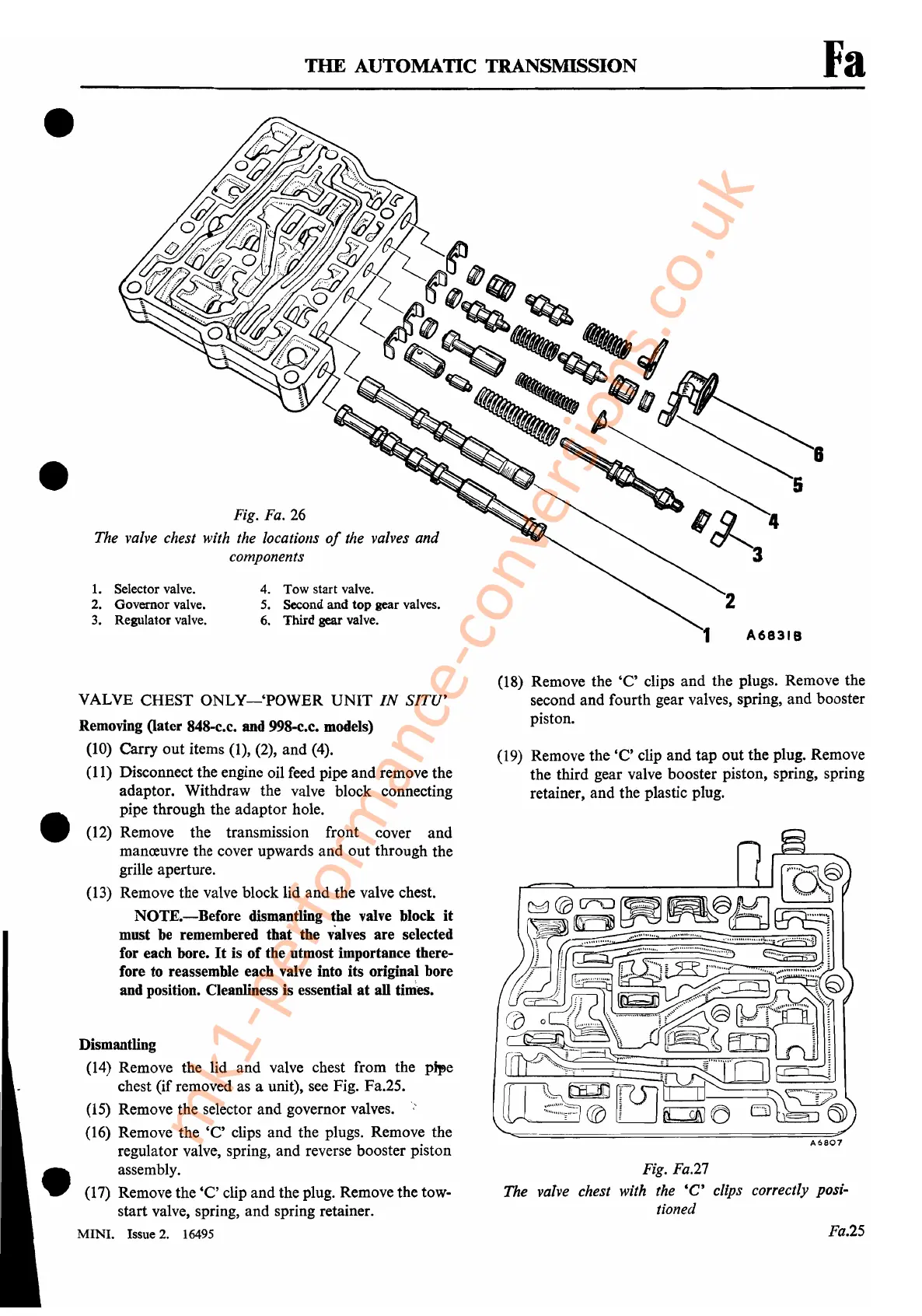
Fig.
Fa.
26
The valve chest with the locations
of
the valves and
components
Fa
8
A6831B
2
4. Tow start valve.
5.
Second and top gear valves.
6.
Third gear valve.
1.
Selector valve.
2. Governor valve.
3. Regulator valve.
•
•
•
•
VALVE CHEST
ONLY-'POWER
UNIT
IN
SITU'
Removing (later 848-c.c. and 998-c.c. models)
(10)
Carry out items (I), (2), and (4).
(11) Disconnect the engine oil feed pipe and remove the
adaptor. Withdraw the valve block connecting
pipe through the adaptor hole.
(12)
Remove the transmission front cover and
manreuvre the cover upwards and out through the
grille aperture.
(13)
Remove the valve block lid and the valve chest.
NOTE.-Before
dismantling the
valve
block
it
must be remembered that the valves are selected
for each bore.
It
is of the utmost importance there-
fore to reassemble each
valve
into its original bore
and position. Cleanliness is essential
at
all tinits.
Dismantling
(14)
Remove the lid and valve chest from the
pt,>e
chest (if removed as a unit), see Fig. Fa.25.
(15)
Remove the selector and governor valves.
(16)
Remove the
'C'
clips and the plugs. Remove the
regulator valve, spring, and reverse booster piston
assembly.
(17)
Remove the
'C'
clip and the plug. Remove the tow-
start valve, spring, and spring retainer.
MINI.
Issue 2.
16495
(18)
Remove the
'C'
clips and the plugs. Remove the
second and fourth gear valves, spring, and booster
piston.
(19)
Remove the
'C'
clip and tap out the plug. Remove
the third gear valve booster piston, spring, spring
retainer, and the plastic plug.
A6807
Fig.
Fa.27
The valve chest with the
'C'
clips correctly posi-
tioned
Fa.25
mk1-performance-conversions.co.uk



 To Next Page