Fa
THE AUTOMATIC TRANSl\fiSSION
,
\
Inspecting
Clean all parts thoroughly in clean fuel (petrol) or
paraffin (kerosene) and dry off using an air pressure line.
Check for burrs on the valves and valve chest and for
sticking valves. Place all components in automatic trans-
mission oil before reassembling to the valve block.
Reassembling
(20)
Reassemble each valve assembly in the reverse
order
of
dismantling
(see
Fig. Fa.26). Check that
the
'C'
clips and plugs are correctly located in the
valve chest (see Fig. Fa.27).
Refitting
(21)
Refitting
is
a reversal
of
the removal procedure;
take care to locate the selector valve with the
linkage and the governor rod with the governor.
The fiat on the governor valve must face inwards.
Tighten all securing bolts to the torque figures
given in
'GENERAL
DATA'.
(22)
Ensure that the new joint washer fitted to the
filter.
head/transmission front cover
is
correctly fitted.
(23)
Check and adjust
if
necessary the gear change
cableand selectorrod adjustment(see Section Fa.2).
(24)
Refill the engine/transmission unit with the recom-
mended oil to the
'MAX'
mark on the dipstick
(see Section Aa.I).
VALVE BLOCK ASSEMBLY REPLACEMENT
'POWER
UNIT
REMOVED'
Removing (later 848-c.c. and 998-c.c. models)
(25)
Remove the engine/transmission unit from the car
(Section Aa.3).
(26)
Remove the converter cover, converter and con-
verter housing as detailed in Section AaA, items
(3)
to
(11).
(27)
Carry out items
(10)
and
(11)
and remove the front
cover.
(28)
Remove all the servo unit securing bolts. •
(29)
Remove the bell-crank lever clevis pin. Unscrew .
and pull out the selector rod.
(30)
Carry out operations
(2)
and
(3)
in Section Fa.5.
A~_
-=-
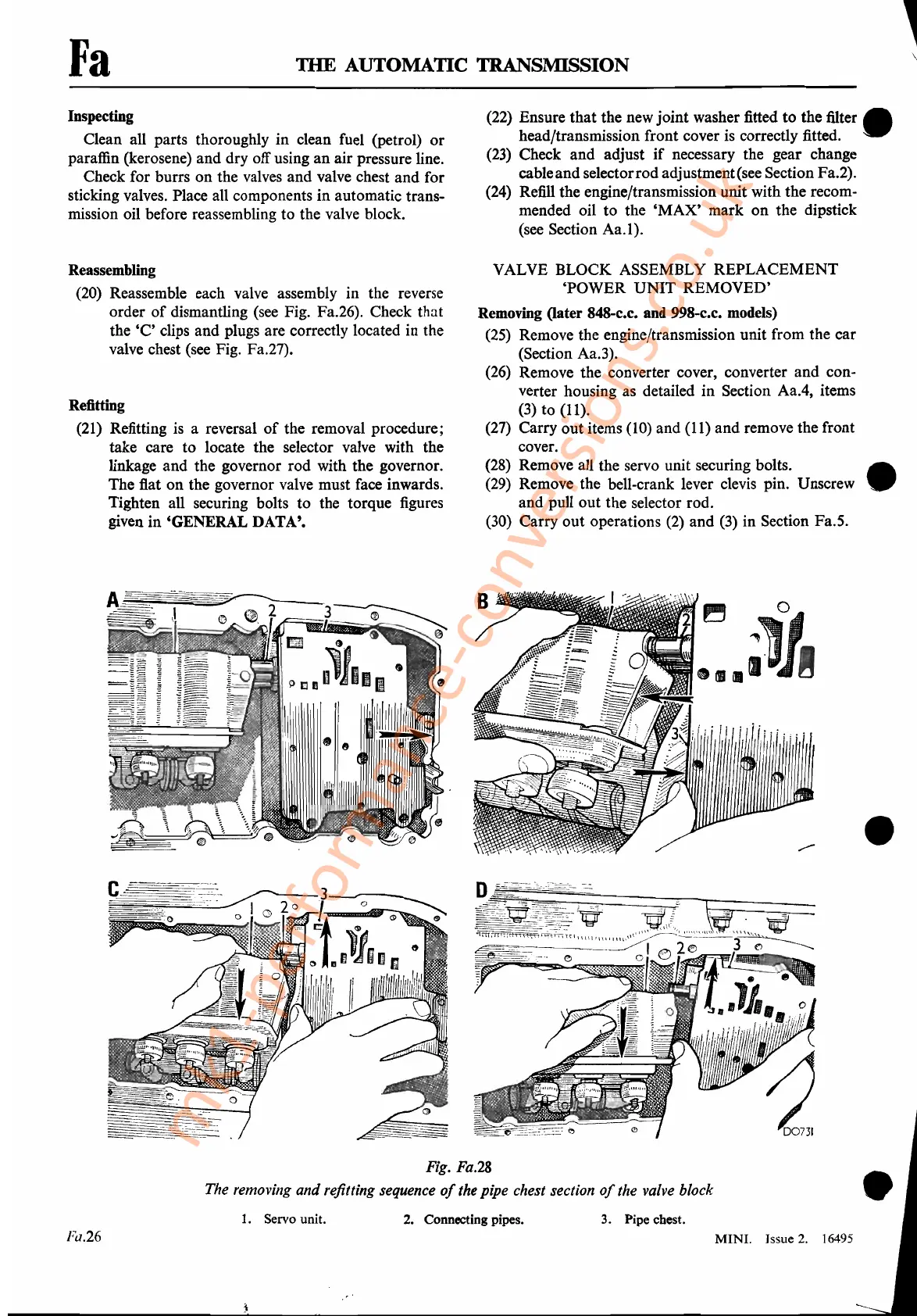
Fig. Fa.28
The removing and refitting sequence
of
the pipe chest section
of
the valve block
•
•
Fa.26
1.
Servo unit.
2. Connecting pipes.
3. Pipe chest.
MINI.
Issue
2.
16495
mk1-performance-conversions.co.uk



 To Next Page