THE AUTOMATIC TRANSMISSION
•
•
•
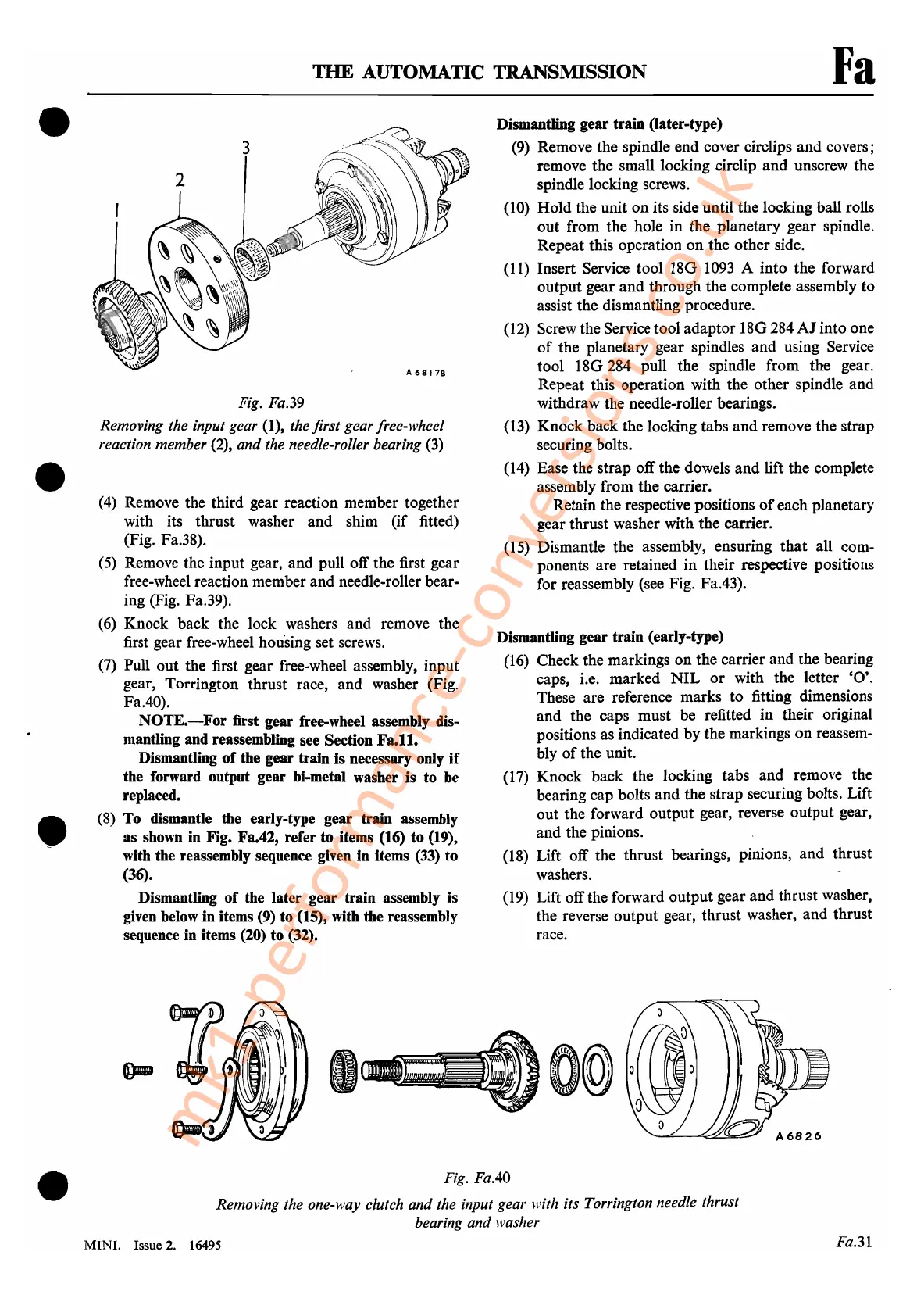
Fig. Fa.39
Removing the input gear
(I), the
first
gear free-wheel
reaction
member
(2),
and
the needle-roller bearing (3)
(4) Remove the third gear reaction member together
with its
thrust
washer
and
shim
(if
fitted)
(Fig. Fa.38).
(5) Remove the
input
gear,
and
pull off the first gear
free-wheel reaction member
and
needle-roller bear-
ing (Fig. Fa.39).
(6)
Knock
back
the
lock washers
and
remove the
first gear free-wheel hou'sing set screws.
(7) Pull
out
the first gear free-wheel assembly,
input
gear, Torrington
thrust
race,
and
washer (Fig.
FaAO).
NOTE.-For
first gear free-wheel assembly dis-
mantling and reassembling see Section
Fa.tt.
Dismantling
of
the gear train is necessary only
if
the forward output gear bi-metal washer is
to
be
replaced.
(8) To dismantle the early-type gear train assembly
as shown in Fig. Fa.42, refer to items
(t6)
to (19),
with the
re
assembly sequence given in items (33) to
(36).
Dismantling
of
the later gear train assembly is
given below in items (9) to
(15), with the reassembly
sequence in items (20) to (32).
Fa
Dismantling
gear
train (later-type)
(9) Remove
the
spindle
end
cover circlips
and
covers;
remove
the
small locking circlip
and
unscrew the
spindle locking screws.
(10)
Hold
the
unit
on
its side until
the
locking ball rolls
out
from
the hole
in
the
planetary
gear
spindle.
Repeat
this operation
on
the
other
side.
(11) Insert Service
tool
180
1093 A
into
the
forward
output
gear
and
through
the complete assembly
to
assist
the
dismantling procedure.
(12) Screw
the
Service
tool
adaptor
180284
AI
into
one
of
the
planetary
gear
spindles
and
using Service
tool
180284
pull
the
spindle
from
the
gear.
Repeat this operation with the
other
spindle
and
withdraw the needle-roller bearings.
(13)
Knock
back
the
locking
tabs
and
remove
the
strap
securing bolts.
(14) Ease
the
strap
off
the
dowels
and
lift
the
complete
assembly
from
the
carrier.
Retain
the
respective positions
of
each planetary
gear
thrust
washer with
the
carrier.
(15) Dismantle the assembly, ensuring
that
all com-
ponents are retained
in
their respective positions
for
reassembly (see Fig. FaA3).
Dismantling gear train (early-type)
(16) Check
the
markings
on
the
carrier
and
the bearing
caps,
Le.
marked
NIL
or
with the letter
'0'.
These
are
reference marks
to
fitting dimensions
and
the caps
must
be refitted
in
their original
positions as indicated
by
the
markings
on
reassem-
bly
of
the unit.
(17)
Knock
back
the
locking tabs
and
remove the
bearing cap bolts
and
the strap securing bolts. Lift
out
the
forward
output
gear, reverse
output
gear,
and
the pinions.
(18) Lift off the
thrust
bearings, pinions,
and
thrust
washers. .
(19) Lift
off
the forward
output
gear
and
thrust
washer,
the reverse
output
gear,
thrust
washer,
and
thrust
race.
•
Fig. FaAO
Removing the one-way clutch
and
the input gear with its Torrington needle thrust
bearing
and
washer
MINI. Issue 2.
16495
Fa.31
mk1-performance-conversions.co.uk



 To Next Page