Fa
TIlE AUTOMATIC TRANSMISSION
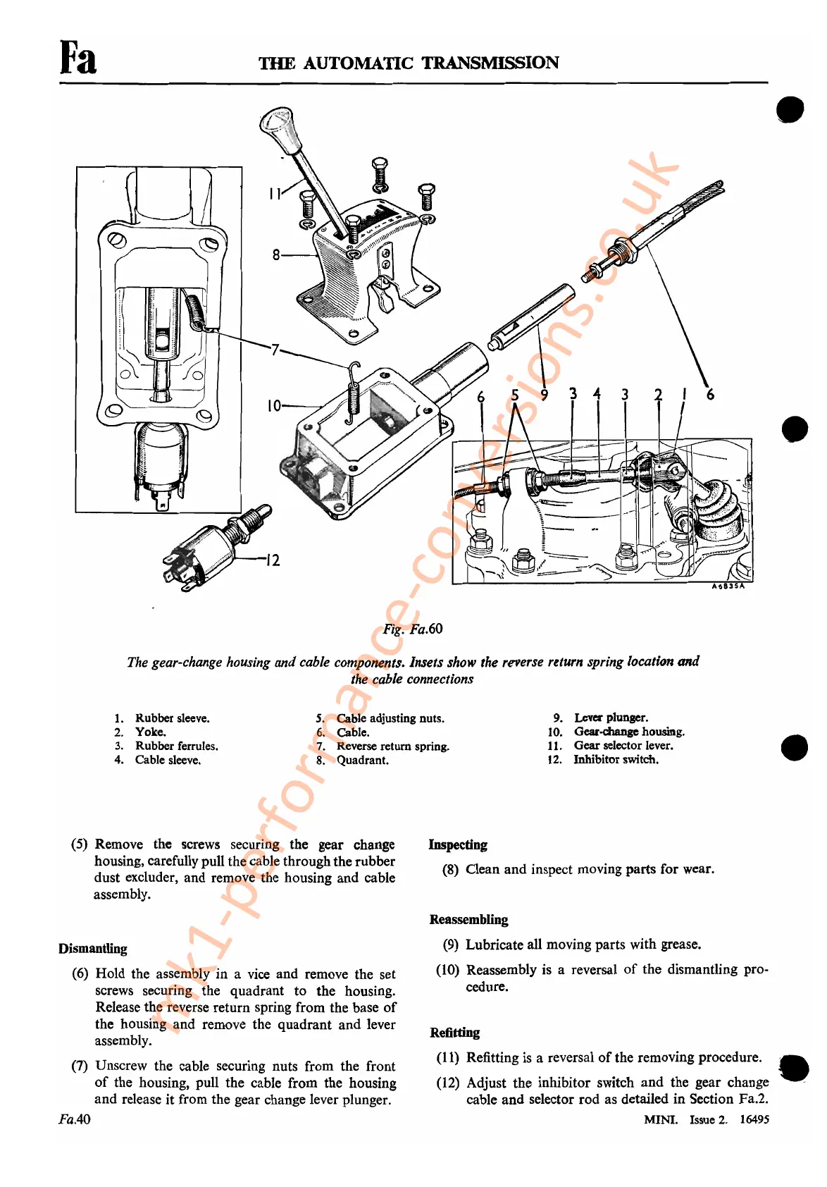
Fig.
Fa.60
•
•
The
gear-change
housing
and
cable
components.
Insets
show
the
reverse
return
spring location
and
the
cable
connections
1. Rubber sleeve.
2. Yoke.
3. Rubber ferrules.
4. Cable sleeve.
S.
Cable adjusting nuts.
6. Cable.
7. Reverse return spring.
8. Quadrant.
9.
Lev«
plunger.
10. Gear.change housing.
11.
Gear
selector lever.
12. Inhibitor switch.
•
(5) Remove the screws securing the gear change
housing, carefully pull the cable through the rubber
dust excluder, and remove the housing and cable
assembly.
Dismantling
(6)
Hold the assembly in a
vice
and remove the set
screws securing the quadrant to the housing.
Release the reverse return spring from the base
of
the housing and remove the quadrant and lever
assembly.
(7)
Unscrew the cable securing nuts from the front
of
the housing, pull the cable from the housing
and release it from the gear change lever plunger.
Fa.40
Inspecting
(8)
Clean and inspect moving parts for wear.
Reassembling
(9)
Lubricate all moving parts with grease.
(lO)
Reassembly is a reversal
of
the dismantling pro-
cedure.
Refitting
(11)
Refitting
is
a reversal
of
the removing procedure.
(12)
Adjust the inhibitor switch and the gear change
cable and selector rod as detailed in Section Fa.2.
MINI. Issue
2.
16495
•
mk1-performance-conversions.co.uk



 To Next Page