THE
REAR SUSPENSION
•
(3) Remove the bump rubber from the sub-frame.
(4) Depressurize the Hydrolastic system (see Section
H.7).
(5)
Disconnect the flexible Hydrolastic hose from its
union
on
the rear face
of
the sub-frame.
(6)
Remove the displacer strut
and
turn
the unit anti-
clockwise
and
withdraw it from the frame.
Section H.9
H
Refitting
(7) Reverse the removal instructions.
(8)
Rotate the displacer clockwise to lock
it
into the
registers
on
the locating plate.
(9) Lubricate the strut ball
and
the nylon seat with
Dextragrease G.P.
and
make sure the dust seal is
fitted over the lip
of
the nylon cup.
(10) Evacuate
and
pressurize the system (Section H.7).
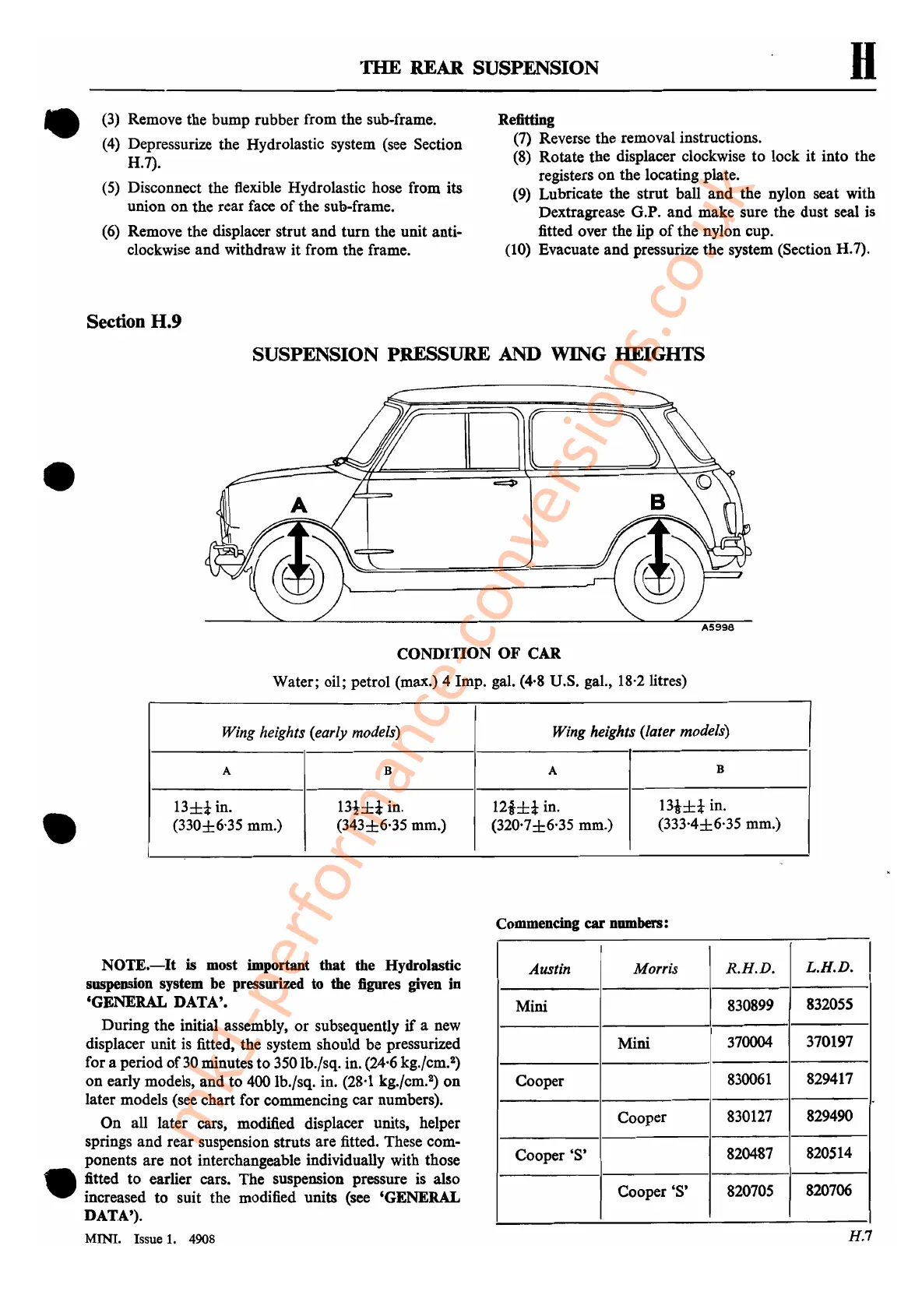
SUSPENSION PRESSURE AND WING HEIGHTS
•
r
•
CONDITION
OF
CAR
Water; oil; petrol (max.) 4 Imp. gal. (4,8 D.S. gal., 18·2 litres)
Wing heights (early models) Wing heights (later models)
A
B
A
B
13±*
in.
13t±i
in.
12i±i
in.
13!±t
in.
(330±6·35 mm.)
(343±6'35 mm.)
(320·7±6·35 mm.)
(333·4±6·35 mm.)
Commencing car numbers:
NOTE.-It
is most important that the Hydrolastic
suspension system be pressurized to the figures given in
'GENERAL DATA'.
During the initial assembly,
or
subsequently
if
a new
displacer unit is fitted, the system should be pressurized
for a period
of30
minutes
to
350 Ib./sq. in. (24,6 kg./cm.
2
)
on
early models,
and
to 400 lb./sq. in. (28,1 kg./cm.
2
)
on
later models (see chart for commencing
car
numbers).
On
all later cars, modified displacer units, helper
springs
and
rear suspension struts are fitted. These com-
ponents are not· interchangeable individually with those
• fitted to earlier cars. The suspension pressure is also
increased to suit the modified units (see 'GENERAL
DATA').
MINI. Issue
1.
4908
Austin
Morris
R.H.D.
L.B.D.
I
Mini
830899
832055
Mini
370004
370197
Cooper
830061
829417
Cooper
830127
829490
Cooper'S'
820487
820514
Cooper'S'
820705
820706
H.7
mk1-performance-conversions.co.uk
 Loading...


