H
THE
REAR SUSPENSION
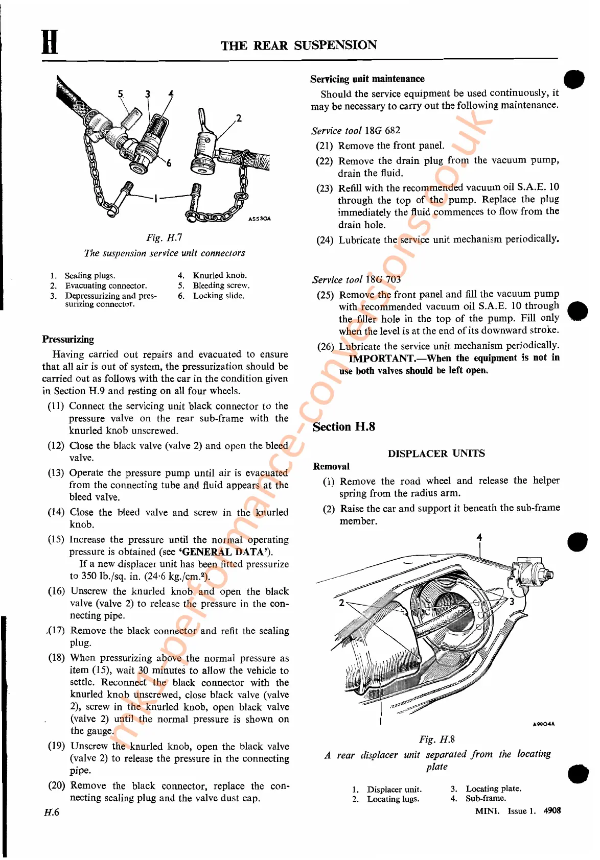
Fig. H.7
The suspension service unit connectors
Servicing unit maintenance •
Should the service equipment be used continuously,
it
may be necessary
to
carry
out
the following maintenance.
Service tool 18G 682
(21) Remove the front panel.
(22) Remove the drain plug from the vacuum pump,
drain the fluid.
(23) Refill with the recommended vacuum oil S.A.E.
10
through the top
of
the pump. Replace the plug
immediately the fluid commences to flow from the
drain hole.
(24) Lubricate the service unit mechanism periodically.
H.6
Pressurizing
Having carried out repairs and evacuated to ensure
that
all air is out
of
system, the pressurization should be
carried out as follows with the car in the condition given
in
Section H.9 and resting on all four wheels.
(11) Connect the servicing unit black connector to the
pressure valve on the rear sub-frame with the
knurled knob unscrewed.
(12) Close the black valve (valve
2)
and open the bleed
valve.
(13)
Operate the pressure pump until air
is
evacuated
from the connecting tube
and
fluid appears
at
the
bleed valve.
(14) Close the bleed valve and screw in the knurled
knob.
(15)
Increase the pressure until the normal operating
pressure is obtained (see 'GENERAL DATA').
If
a new displacer unit has been fitted pressurize
to
350
lb.jsq. in. (24,6 kg.jcm.
2
).
(16) Unscrew the knurled knob and open the black
valve (valve
2)
to release the pressure in the con-
necting pipe.
.(17) Remove the black connector
and
refit the sealing
plug.
(18)
When pressurizing above the normal pressure as
item (15), wait
30
minutes to allow the vehicle to
settle. Reconnect the black connector with the
knurled knob unscrewed, close black valve (valve
2), screw in the knurled knob, open black valve
(valve
2)
until the normal pressure is shown on
the gauge.
(19) Unscrew the knurled knob, open the black valve
(valve
2)
to release the pressure in the connecting
pipe.
(20) Remove the black connector, replace the con-
necting sealing plug and the valve dust cap.
A9904"
•
•
•
3.
Locating plate.
4.
Sub-frame.
MINI. Issue
1.
4908
1.
Displacer unit.
2.
Locating lugs.
DISPLACER UNITS
Service tool 18G 703
(25) Remove the front panel
and
fill
the vacuum pump
with recommended vacuum oil S.A.E.
10
through
the filler hole in the
top
of
the pump. Fill only
when the level is
at
the end
of
its downward stroke.
(26) Lubricate the service unit mechanism periodically.
IMPORTANT.-When
the equipment is not in
use both valves should be left open.
-4
Fig. H.8
A rear displacer unit separated from. the locating
plate
Removal
(l)
Remove the road wheel
and
release the helper
spring from the radius arm.
(2) Raise the car and support
it
beneath the sub-frame
member.
Section H.8
4. Knurled knob.
5.
Bleeding screw.
6.
Locking slide.
1.
Sealing plugs.
2.
Evacuating connector.
3.
Depressurizing and pres-
surizing connector.
mk1-performance-conversions.co.uk
 Loading...


