•
•
THE
REAR SUSPENSION
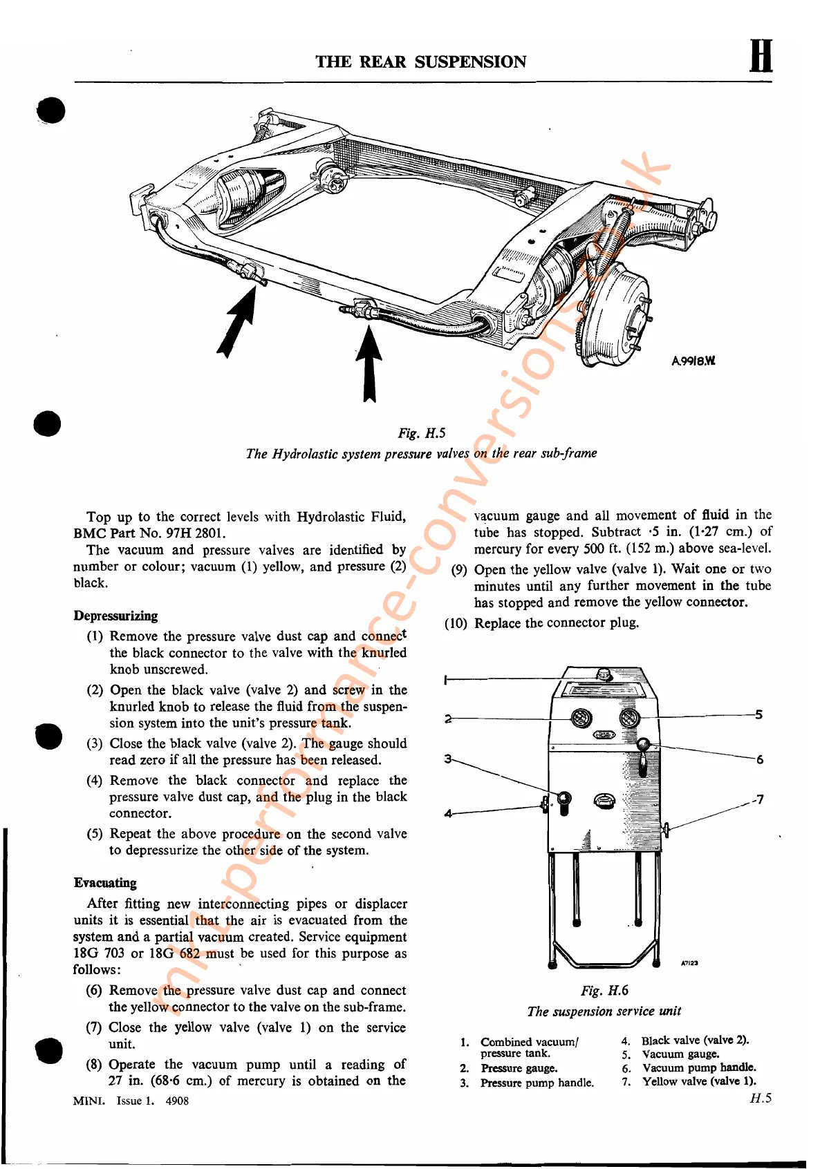
Fig. H.5
The Hydrolastic system pressure valves on the rear sub-frame
A991e.W
H
vacuum gauge and all movement
of
fluid in the
tu"be
has stopped. Subtract ·5 in. (1,27 cm.) of
mercury for every
500
et.
(152
m.) above sea-level.
(9) Open the yellow valve (valve 1). Wait one
or
two
minutes until any further movement in the tube
has stopped and remove the yellow connector.
(10)
Replace the connector
pI
ug.
Fig. H.6
The suspension service unit
•
•
Top up to the correct levels with Hydrolastic Fluid,
BMC Part No. 97H 2801.
The vacuum and pressure valves are identified by
number or colour; vacuum
(1) yellow, and pressure (2)
black.
Depressurizing
(1) Remove the pressure valve dust cap and connect
the black connector to the valve with the knurled
knob unscrewed.
(2) Open the black valve (valve 2) and screw in the
knurled knob to release the fluid from the suspen-
sion system into the unit's pressure tank.
(3) Close the black valve (valve 2). The gauge should
read zero if all the pressure has been released.
(4) Remove the black connector and replace the
pressure valve dust cap, and the plug in the black
connector.
(5) Repeat the above procedure on the second valve
to depressurize the other side
of
the system.
Evacuating
After fitting new interconnecting pipes or displacer
units
it
is essential that the air is evacuated from the
system and a partial vacuum created. Service equipment
180
703
or
18G
682
must be used for this purpose as
follows: '
«(»
Remove the pressure valve dust cap and connect
the yellow connector to the valve on the sub-frame.
(7) Close the yellow valve (valve 1) on the service
unit.
(8)
Operate the vacuum pump until a reading
of
27 in. (68,6 cm.)
of
mercury
is
obtained on the
MINI.
Issue
1.
4908
4--~
1.
Combined vacuumJ
pressure tank.
2. Pressure gauge.
3.
Pressure pump handle.
nal--!-------s
6
./"-7
.1.7123
4. Black valve (valve 2).
5. Vacuum gauge.
6. Vacuum pump handle.
7. Yellow valve (valve 1).
H.5
mk1-performance-conversions.co.uk
 Loading...


