THE
REAR SUSPENSION
•
•
•
•
HYDROLASTIC
SUSPENSION
DEPRESSURIZING, EVACUATING, AND
PRES·
SURIZING
THE
HYDROLASTIC SYSTEM
Section H.7
The system consists
of
two front
and'
two rear dis-
placer units intercoupled longitudinally. Each is made
of
sheet steel and rubber and consists
of
a piston, a dia-
phragm, a lower
and
upper chamber housing,
and
a
conical spring
of
compressed rubber.
Contact
of
the front wheels with a road irregularity
forces the piston to push the diaphragm up; increased
pressure displaces some
of
the fluid from the bottom
chamber to the top chamber. The rubber springs deflect
due to
th~
pressure increase and fluid displacement, and
the resultant pressure increase causes fluid to discharge
through the interconnecting pipe into the rear displacer
unit.
The fluid entering the rear displacer forces the dia-
phragm to react against the piston, resulting
in
the car
height
at
the rear being raised. These events are virtually
simultaneous
and
the car therefore rides
an
obstruction
without pitch motion
of
the body. The action
of
the
suspension is similar when the
rear
wheels negotiate the
irregularity.
The fluid used
in
the system
is
a mixture
of
water and
alcohol into which an anti-corrosive agent has been
introduced.
The front suspension also comprises upper
and
lower
arms
of
unequal length located
in
the side-members
of
the front sub-frame with their outer ends attached by
ball joints to the swivel hubs.
The rear suspension, in addition to the Hydrolastic
units, consists
of
independent trailing arms with auxiliary
coil springs.
Section H.6
Before any major work can be carried out
on
the
suspension
and
its components the Hydrolastic system
must be depressurized and in some cases evacuated.
For
this operation Service equipment
Part
No. 18G
703
or
18G 682 must be connected to the pressure valves
on
the
rear sub-frame.
Before using Service equipment 18G
703
check
that
the pressure/vacuum
tank
is
filled to the level indicated
at
the rear
of
the unit. The vacuum
and
pressure valves
are indentified by colour only; vacuum (yellow)
and
pressure (black).
Early service equipment (18G 682) has separate fillers
for the pressure
and
vacuum tanks
and
are filled to the
level shown
on
the dipstick. One side
of
the dipstick
shows the level in the pressure
tank
and
the other side
the level in the vacuum tank.
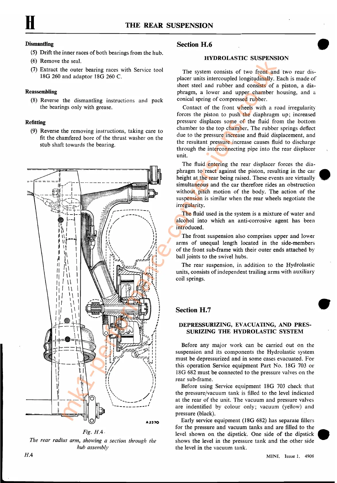
Fig.
HA·
The rear radius arm, showing a section through the
hub
assembly
Dismantling
(5) Drift the inner races
of
both bearings from the hub.
(6)
Remove the seal.
(7)
Extract the outer bearing races with Service tool
18G 260
and
adaptor 18G 260
C.
Reassembling
(8)
Reverse the dismantling instructions and pack
the bearings only with grease.
Refitting
(9) Reverse the removing instructions, taking care to
fit the chamfered bore
of
the thrust washer
on
the
stub shaft towards the bearing.
H
HA
MINI.
Issue
1.
4908
mk1-performance-conversions.co.uk
 Loading...


