THE
REAR SUSPENSION
H
Rear
(4)
Jack up the car
at
a point between the bumper
and the rear body panel.
(5)
Withdraw the mounting block to body screws and
remove the nut from the end
of
the mounting
support pin.
(6)
Prise the body and frame apart sufficiently to
allow the block and rubbers to be removed.
Refitting
(7)
Reverse the removing instructions. Insert the
mounting block to body screws before tightening
the support pin nut.
•
Fig.
H.2
Extract the strut from the spring unit and pull
it
rearwards to disengage the ball end from the radius
arm
Section H.3
SPRING UNITS
Removing
(1)
Carry out instructions (1) to
(3)
and
(5)
in Section
H.2.
Section H.5
HUB
Removing
(l)
Jack up the car and remove the road wheel and the
brake-drum.
(2)
Prise off the hub cap.
(3)
Extract the split pin and
screw
the nut from the
end
of
the stub shaft.
(4)
Withdraw the hub assembly.
•
•
(2)
Remove the spring unit.
(3)
Prise out the nylon seating.
Refitting
(4)
Reverse the removing instructions, but note:
(5)
Make sure that the spring unit and spring strut
are correctly located in their spigots while the
radius arm is being raised to connect the upper
end of the damper.
Section H.4
SUB-FRAME MOUNTINGS
Removing
(l)
Jack up the car at a point near the bumper and the
rear btidy panel.
Front
(2)
Remove the radius arm (Section H.2).
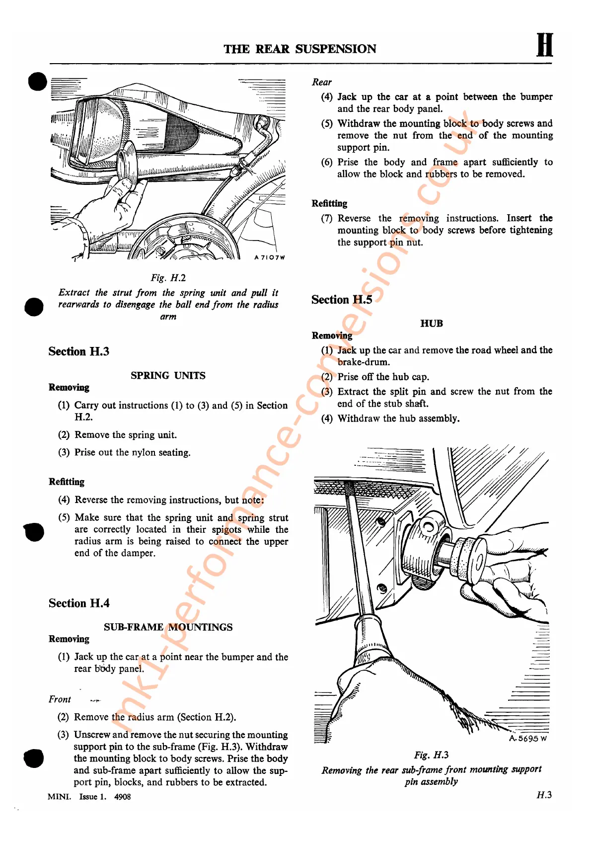
(3)
Unscrew and remove the nutsecuring the mounting
support pin to the sub-frame (Fig. H.3). Withdraw
the mounting block to body screws. Prise the body
and sub-frame apart sufficiently to allow the sup-
port pin, blocks, and rubbers to be extracted.
MINI. Issue 1. 4908
Fig.
H.3
Removing the rear sub-frame front mounting support
pin assembly
H.3
mk1-performance-conversions.co.uk
 Loading...


