I
THE FRONT SUSPENSION
Section K.2
Refitting
(10) Reverse the removing instructions.
SWIVEL HUBS
Remo~g
•
(1)
Jack up and remove the road wheel.
..
.
(2)
Remove the steering ball joint nut;
to
release the
ball joint from the steering lever use Service tool
180
1063.
•
(7)
With the spring unit compressed, lever the strut •
from the spring unit.
(8)
Detach the hydraulic damper, dismantle the upper
arm pivot and remove the upper arm.
(9)
Hold the centre screw
of
the tool
to
prevent it
turning, screw the ratchet handle upwards
to
re-
lease the spring compression, remove the tool,
and
extract the spring unit from the tower.
(3)
Disconnect the drive shaft at the inner flexible joint
undoing only the four outer
'U'
-bolts and after
marking the flange and jointfor correct reassembly.
(4)
Disconnect the brake hose from the backplate.
(5)
Remove the upper suspension arm retaining
nut
and spring washer and release the arm from the pin
using Service tool
180
1063.
(6)
Disconnect the tie-rod from the lower arm;
to
re-
lease the hub from the arm use Service tool
180
1063.
(7)
Withdraw the hub and drive shaft.
Dismantling
(8)
Remove the brake-drum.
(9)
Remove the split pin, nut, and distance washer and
drive the shaft from the flange and hub.
(10) Remove the drive shaft with Service tool
180304,
using adaptor bolts
180304
F. Remove the driving
flange from the hub with Service tool
180
575.
(11) Remove the inner and outer seal
and
the outer
bearing spacer.
(12) Drift out the inner race
of
each bearing, and use
Service tools
180
260 H
to
withdraw the outer
races.
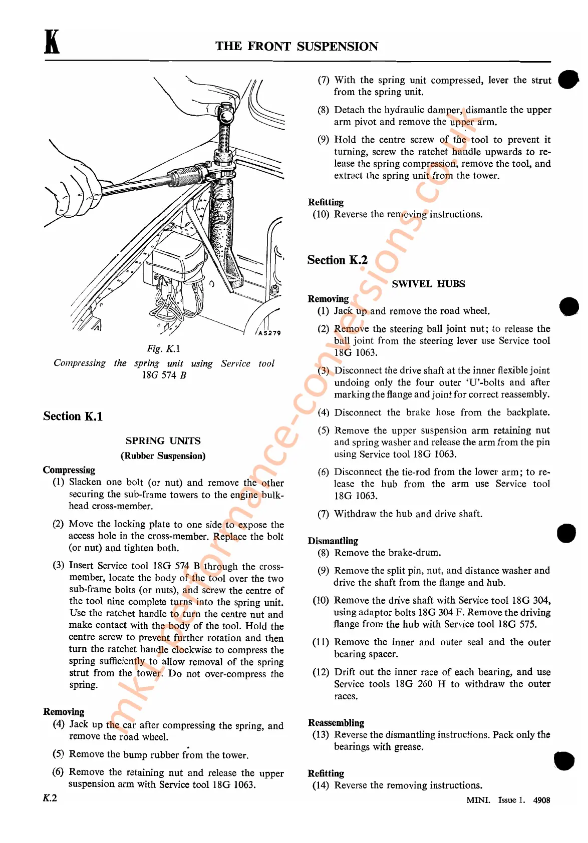
Fig.
K.l
Compressing the spring unit using Service tool
18G
574
B
SPRING
UNITS
(Rubber Suspension)
Section
K.l
Compressing
(1)
Slacken one bolt (or nut) and remove the other
securing the sub-frame towers to the engine bulk-
head cross-member.
(2)
Move the locking plate to one side to expose the
access hole in the cross-member. Replace the bolt
(or nut) and tighten both.
(3)
Insert Service tool
180
574
B through the cross-
member, locate the body
of
the tool over the two
sub-frame bolts (or nuts), and screw the centre
of
the tool nine complete turns into the spring unit.
Use the ratchet handle
to
turn the centre nut and
make contact with the body
of
the tool. Hold the
centre screw to prevent further rotation and then
turn
the ratchet handle clockwise to compress the
spring sufficiently to allow removal
of
the spring
strut from the tower.
Do
not over-compress the
spring.
•
Removing
(4) Jack up the car after compressing the spring, and
remove the road wheel.
(5)
Remove the bump rubber f;om the tower.
(6) Remove the retaining
nut
and release the upper
suspension arm with Service tool
180
1063.
K.2
Reassembling
(13) Reverse the dismantling instructions. Pack only the
bearings with grease.
Refitting
(14) Reverse the removing instructions.
MINI. Issue
1.
4908
mk1-performance-conversions.co.uk