•
•
THE
FRONT
SUSPENSION
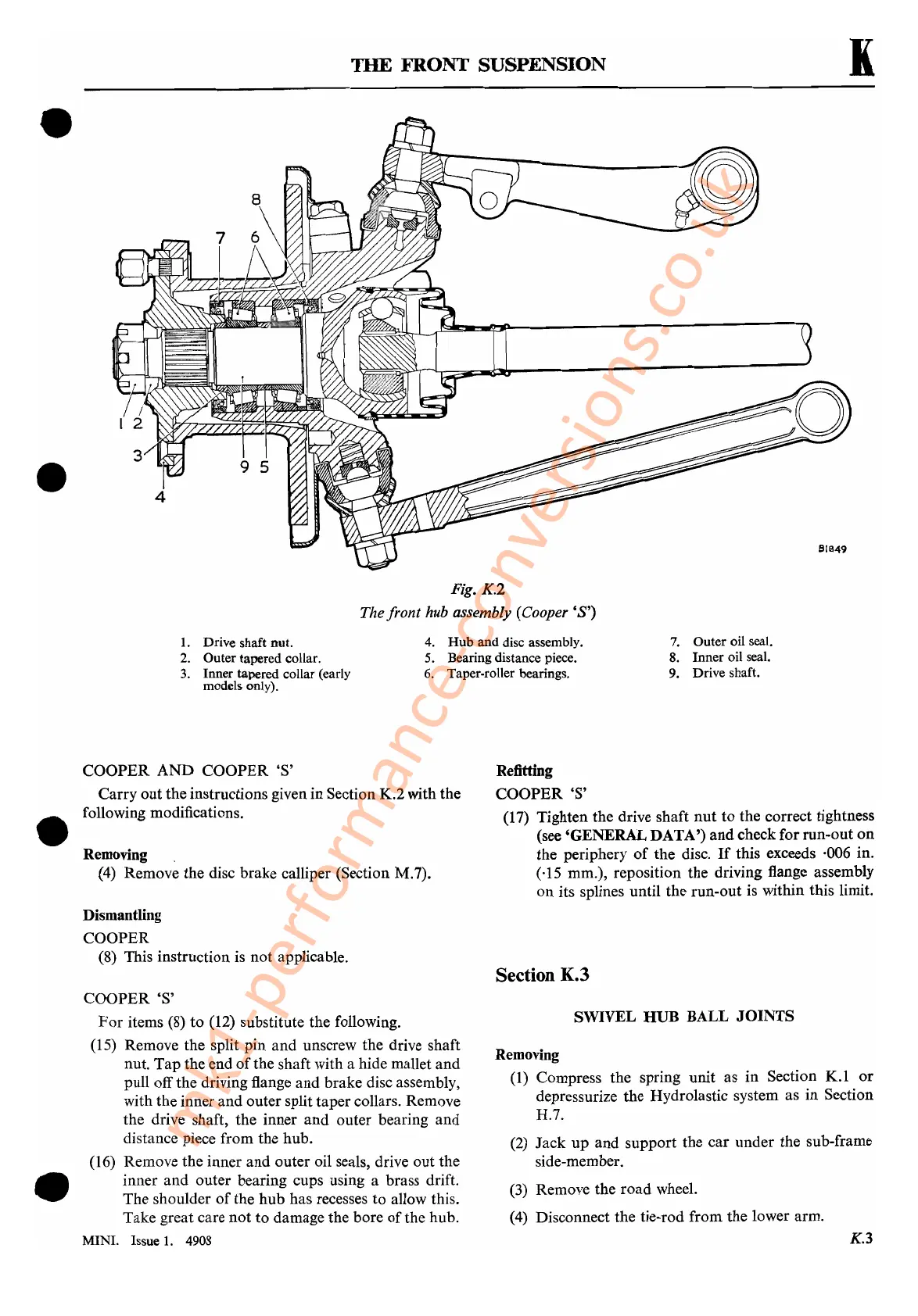
Fig. K.2
The front hub assembly (Cooper'S')
1.
Drive shaft nut.
2. Outer tapered collar.
3.
Inner tapered collar (early
models only).
4.
Hub
and disc assembly.
5.
Bearing distance piece.
6. Taper-roller bearings.
7. Outer oil seal.
8. Inner oil seal.
9. Drive shaft.
•
•
COOPER
AND
COOPER'S'
Carry out the instructions given in Section K.2 with the
following modifications.
Removing
(4)
Remove the disc brake calliper (Section M.7).
Dismantling
COOPER
(8) This instruction is not applicable.
COOPER'S'
For
items
(8)
to
(12) substitute the following.
(15) Remove the split pin
and
unscrew the drive shaft
nut.
Tap
the end
of
the shaft with a hide mallet and
pull off the driving flange
and
brake disc assembly,
with the inner
and
outer split taper collars. Remove
the drive shaft, the inner
and
outer bearing and
distance piece from the hub.
(16) Remove the inner
and
outer oil seals, drive out the
inner and outer bearing cups using a brass drift.
The shoulder
of
the hub has recesses to allow this.
Take great care not
to
damage the bore
of
the hub.
MINI. Issue
1.
4908
Refitting
COOPER'S'
(17) Tighten the drive shaft
nut
to the correct tightness
(see 'GENERALDATA')
and
check for run-out
on
the periphery
of
the disc.
If
this exceeds ·006 in.
(,15 mm.), reposition the driving flange assembly
on
its splines until the run-out is within this limit.
Section K.3
SWIVEL
HUB
BALL
JOINTS
Removing
(1)
Compress the spring unit as
in
Section
K.l
or
depressurize the Hydrolastic system as
in
Section
H.7.
(2)
Jack
up
and support the car under the sub-frame
side-member.
(3)
Remove the road wheel.
(4) Disconnect the tie-rod from the lower arm.
K.3
mk1-performance-conversions.co.uk
 Loading...


