K
THE FRONT SUSPENSION
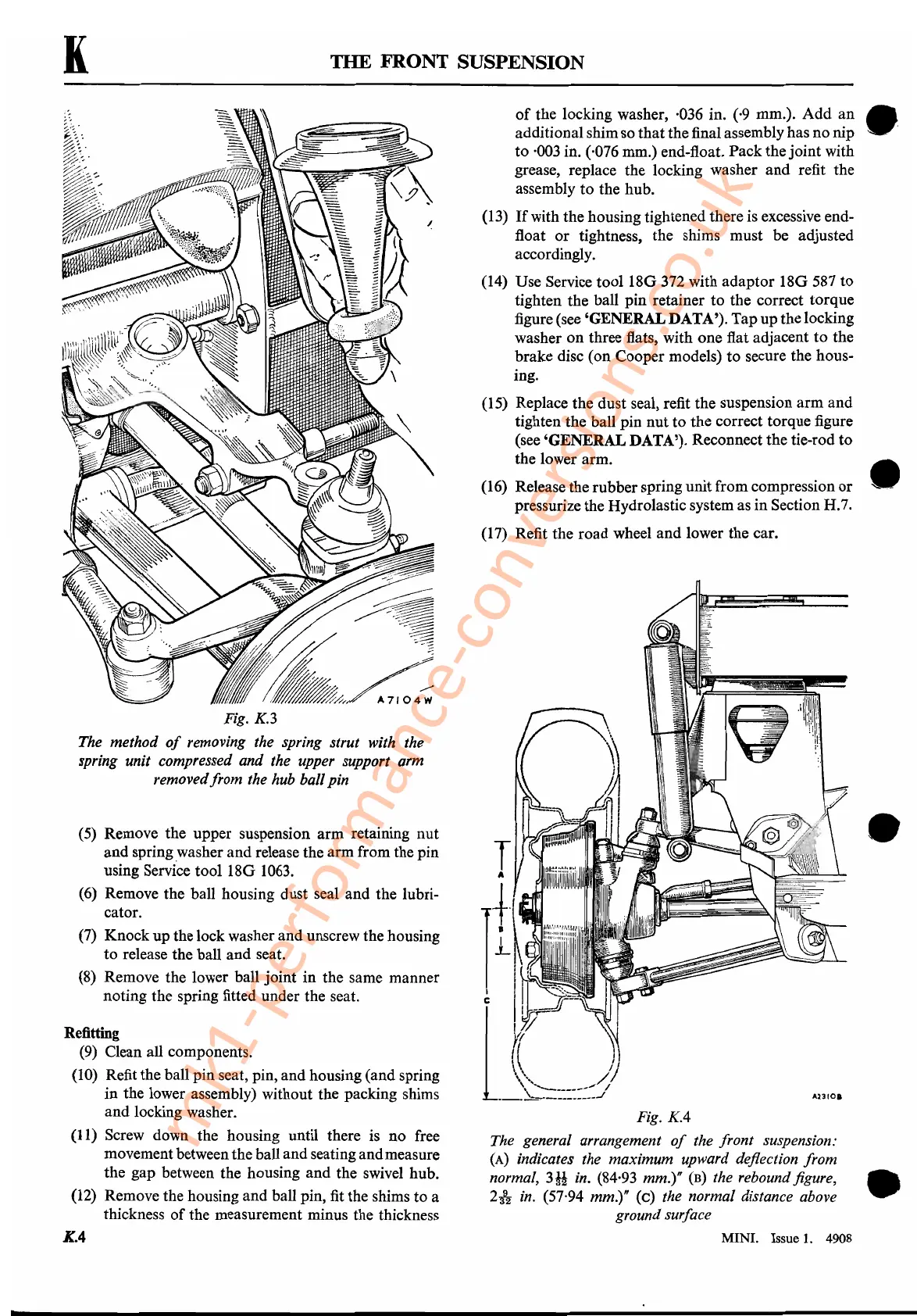
Fig.
KA
The general arrangement
of
the front suspension:
(A)
indicates the maximum upward deflection from
normal,
3H
in. (84,93 mm.)"
(B)
the rebound figure, •
212-
in.
(57,94 mm.)" (c) the normal distance above
ground surface
Fig.
K.3
The method
of
removing the spring strut with the
spring unit compressed and the upper support arm
removedfrom the hub ballpin
(5)
Remove the upper suspension arm retaining nut
and spring,washer and release the arm from the pin
using Service tool
180
1063.
(6)
Remove the ball housing dust seal and the lubri-
cator.
(7) Knock up the lock washer and unscrew the housing
to release the ball and seat.
(8) Remove the lower ball joint in the same manner
noting the spring fitted under the seat.
Refitting
(9)
Clean all components.
(10)
Refit the ball pin seat, pin, and housing (and spring
in the lower assembly) without the packing shims
and locking washer.
(11) Screw down the housing until there is no free
movement between the ball and seatingandmeasure
the gap between the housing and the swivel hub.
(12) Remove the housing and ball pin, fit the shims to a
thickness
of
the measurement minus the thickness
of
the locking washer, ·036 in. (,9 mm.). Add an
additional shim so thatthe final assembly has no nip
to
·003
in. (,076 mm.) end-float. Pack the joint with
grease, replace the locking washer
and
refit the
assembly to the hub.
(13)
If
with the housing tightened there is excessive end-
float
or
tightness, the shims must be adjusted
accordingly.
(14) Use Service tool
180
372 with adaptor
180587
to
tighten the ball pin retainer to the correct torque
figure (see 'GENERALDATA'). Tapup the locking
washer
on
three flats, with one flat adjacent
to
the
brake disc (on Cooper models) to secure the hous-
ing.
(15) Replace the dust seal, refit the suspension arm and
tighten the ball pin nut to the correct torque figure
(see 'GENERAL DATA'). Reconnect the tie-rod to
the lower arm.
(16) Release the rubberspring unit from compression
or
pressurize the Hydrolastic system as in Section H.7.
(17) Refit the road wheel and lower the car.
e·
•
•
K.4
MINI. Issue
1.
4908
mk1-performance-conversions.co.uk
 Loading...


