M
2
THE
BRAKING SYSTEM
3
4
•
13
12
I J
10
9 8
7
6
5
A4887
•
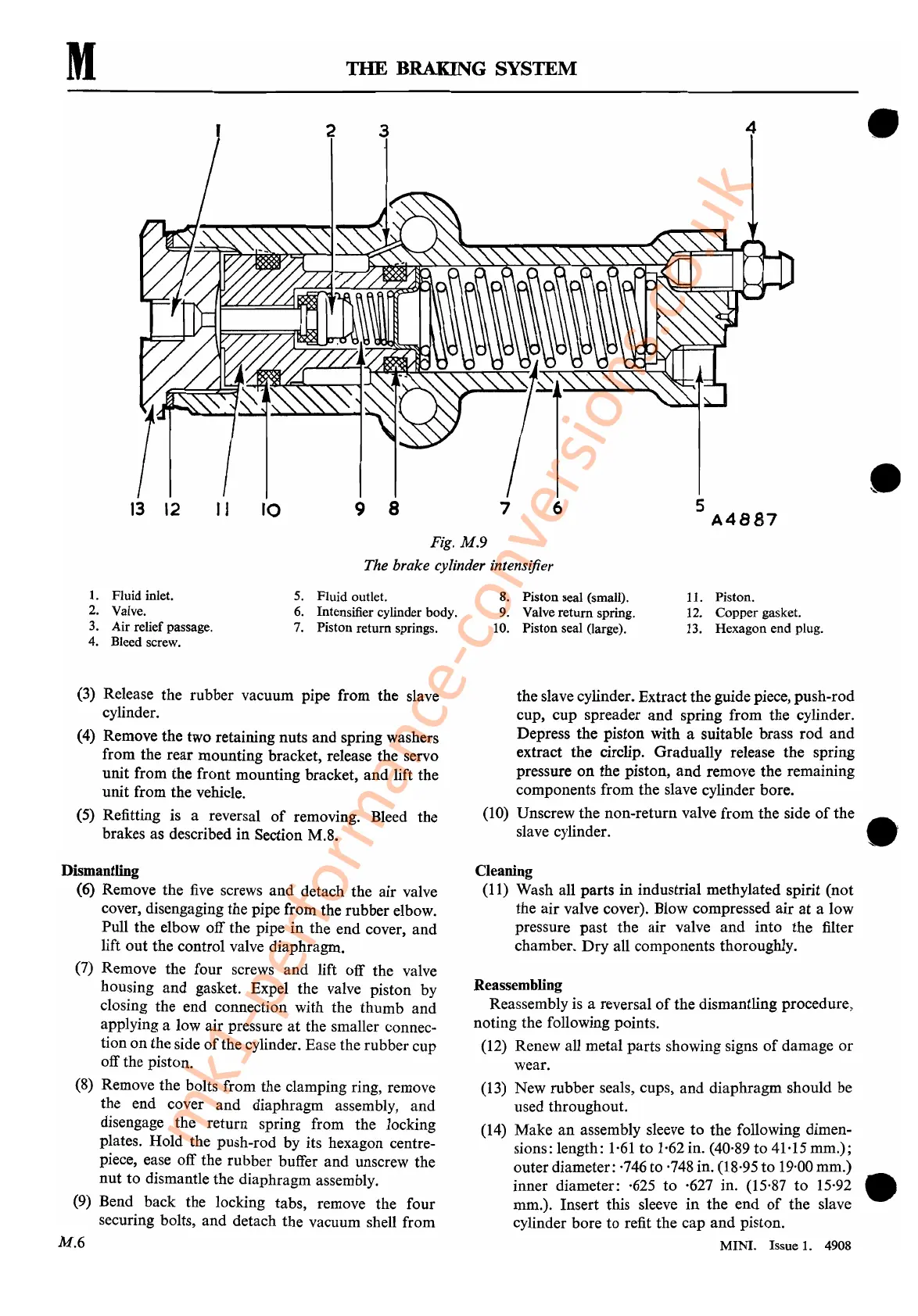
Fig.
M.9
The brake cylinder intensifier
1.
Fluid inlet.
2. Valve.
3.
Air relief passage.
4. Bleed screw.
5. Fluid outlet.
6. Intensifier cylinder body.
7.
Piston return springs.
8.
Piston seal (small).
9. Valve return spring.
10. Piston seal (large).
11. Piston.
12. Copper gasket.
13. Hexagon end plug.
(3)
Release the rubber vacuum pipe from the slave
cylinder.
(4) Remove the two retaining nuts and spring washers
from the rear mounting bracket, release the servo
unit from the front mounting bracket, and lift the
unit from the vehicle.
(5) Refitting is a reversal
of
removing. Bleed the
brakes as described
in
Section M.8.
Dismantling
(6) Remove the
five
screws and detach the air valve
cover, disengaging the pipe from the rubber elbow.
Pull the elbow off the pipe
in
the end cover, and
lift out the control valve diaphragm.
(7)
Remove the four screws and lift off the valve
housing and gasket. Expel the valve piston by
closing the end connection with the thumb and
applying a low air pressure
at
the smaller connec-
tion on the side
of
the cylinder. Ease the rubber cup
off the piston.
(8)
Remove the bolts from the clamping ring, remove
the end cover and diaphragm assembly, and
disengage the return spring from the locking
plates. Hold the push-rod by its hexagon centre-
piece, ease off the rubber buffer and unscrew the
nut
to dismantle the diaphragm assembly.
(9)
Bend back the locking tabs, remove the four
securing bolts, and detach the vacuum shell from
M.6
the slave cylinder. Extract the guide piece, push-rod
cup, cup spreader
and
spring from the cylinder.
Depress the piston with a suitable brass
rod
and
extract the circlip. Gradually release the spring
pressure
on
the piston,
and
remove the remaining
components from the slave cylinder bore.
(10) Unscrew the non-return valve from the side
of
the
slave cylinder. •
Cleaning
(11)
Wash all parts
in
industrial methylated spirit (not
the air valve cover). Blow compressed air
at
a low
pressure past the air valve
and
into the filter
chamber.
Dry
all components thoroughly.
Reassembling
Reassembly is a reversal
of
the dismantling procedure,
noting the following points.
(12) Renew all metal parts showing signs
of
damage
or
wear.
(13)
New rubber seals, cups, and diaphragm should be
used throughout.
(14) Make
an
assembly sleeve
to
the following dimen-
sions: length:
1·61
to
1·62 in. (40,89 to 41·15 mm.);
outer diameter:
·746 to ·748 in. (18,95 to 19·00mm.)
inner diameter: ·625
to
·627 in. (15'87
to
15·92 •
mm.). Insert this sleeve
in
the end
of
the slave
cylinder bore to refit the cap
and
piston.
MINI.
Issue
1.
4908
mk1-performance-conversions.co.uk