THE
BRAKING SYSTEM
•
•
(15)
Take
extreme care
not
to
damage
the
surface finish
of
the
push-rod when reassembling
the
diaphragm.
Lock the securing
nut
by
punching
the
threads
in
two opposed places.
(16)
Do
not
tighten
the
end
cover clamp
bolt
fully until
the
air
valve cover
has
been fitted
and
the
pipe in
the
end
cover is lined
up
with the pipe
and
rubber
elbow
on
the air valve cover.
(17) Check
that
the
diaphragm spring
has
its smaller
end
engaged
under
the
locking plate tabs.
Section M.tO
TWO-LEADING-SHOE
FRONT
BRAKES
Each
front
brake
has
two squared adjusters projecting
from
the
rear
face
of
the backplate, one adjuster for each
brake-shoe.
M
..
A1560
Fig.
M.l1
The hand brake cable sector mounted on the rear
radius arms. Only the corners indicated must be
'nipped' to position the cable
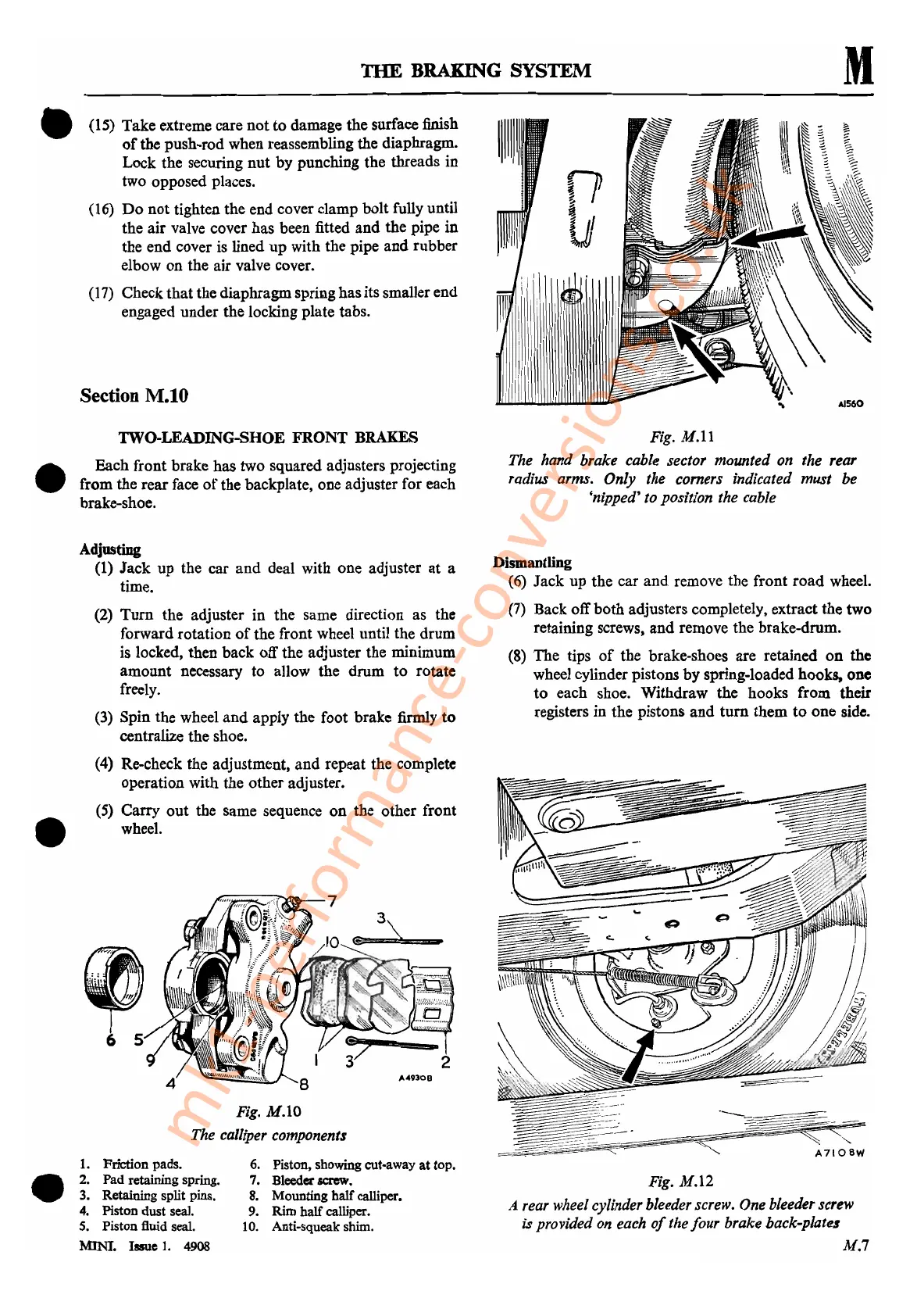
Fig. M.lO
The calliper components
Adjusting
(1)
Jack
up
the
car
and
deal with one adjuster
at
a
time.
(2)
Turn
the adjuster in the same direction as
the
forward rotation
of
the
front wheel until the
drum
is locked,
then
back
off the adjuster the minimum
amount
necessary
to
allow
the
drum
to
rotate
freely.
(3) Spin
the
wheel
and
apply
the
foot
brake
firmly
to
centralize
the
shoe.
(4) Re-check
the
adjustment,
and
repeat the complete
operation with
the
other
adjuster.
(5)
Carry
out
the same sequence
on
the other front
wheel.
Fig. M.12
A rear wheel cylinder bleeder screw. One bleeder screw
is provided on each
of
the four brake back-plates
M.7
Dismantling
(6)
Jack
up
the
car
and
remove the
front
road
wheel.
(7) Back
off
both
adjusters completely, extract
the
two
retaining screws,
and
remove the brake-drum.
(8)
The
tips
of
the
brake-shoes are retained
on
the
wheel cylinder pistons
by
spring-loaded hooks,
one
to
each shoe. Withdraw
the
hooks
from
their
registers
in
the
pistons
and
turn
them
to
one
side.
6. Piston, showing cut-away
at
top.
7.
Bleeder
screw.
8.
Mounting half calliper.
9.
Rim
half
calliper.
10.
Anti-squeak shim.
1.
Friction
pads.
2.
Pad
retaining spring.
3. Retaining split pins.
4. Piston
dust
seal.
S. Piston fluid seal.
MINI. Issue
1.
4908
,
.v~~~
::t-.
_
~"
6 5
•
•
mk1-performance-conversions.co.uk