THE
ELECTRICAL SYSTEM
•
•
•
•
-
...
A6689
Fig. N.9
Alternator output test connections
(a) Zero reading: Stop the engine. Remove and
inspect the brush gear (see 'Inspection'). Fit
new brush gear
if
necessary and retest.
If
zero
reading persists, remove and dismantle the
alternator for detailed inspection.
(b) Low reading: Indicates either a faulty alter-
nator
or
poor
wiring circuit connections.
Stop the engine and check the wiring
connections. Connect a voltmeter (low range)
between the alternator output terminal 'B'
and the battery negative
(-)
terminal,
restart the engine and note the reading.
Transfer the voltmeter connections to the
alternator frame and the battery earth
(+)
terminal and note the reading.
If
either reading exceeds
·5
volt there is
high resistance in the charging circuit which
mllst be traced and remedied. Should the test
show no undue resistance (although output
is
low) proceed to dismantle and inspect the
alternator.
Section N.12
DISMANTLING AND OVERHAULING
THE
llAC
ALTERNATOR
Removing
(1) Disconnect the battery and detach the electrical
leads from the alternator.
(2)
Slacken the alternator securing bolts, push the
alternator towards the engine and detach the
driving belt from the alternator pulley. Remove the
securing bolts and detach the alternator from the
engine.
Dismantling
(3)
Remove the securing
nut
and detach the drive
pulley, fan, and key from the armature shaft.
(4)
Mark
the relative positions
of
the drive end
bracket, the stator lamination pack, and the slip-
ring end bracket for correct reassembly.
MINI. Issue
1.
14091
N
(5)
Remove the through-bolts and detach the drive end
bracket and rotor.
The drive end bracket
and
rotor need not be
separated unless the drive end bearing requires
examination
or
the rotor is
to
be replaced. Remove
the rotor from the drive end bracket by means
of
a hand press having first removed the shaft key and
bearing collar.
(6)
Remove the terminal nuts, brush box retaining
screws, and the heat sink bolt. Withdraw the stator
and heat sink from the slip-ring end bracket.
(7)
Close the retaining tongues
on
the brush terminal
blades and withdraw the terminals from the brush
box.
Inspection
Brush gear
Brushes worn below
-&
in.
(8
mm.) should be replaced.
(a) The new brush complete with spring
and
'Lucar'
terminal blade is pushed into the holder until the
tongue registers.
To
retain the terminal, carefully
lever up the retaining tongue with a thin blade.
(b) Check that the brushes move freely in their
holders.
If
sluggish, clean brush sides with a
petrol-moistened cloth or,
if
ineffective, lightly
polish brush sides with a smooth
file.
Clean off
and re-house.
Slip-rings
Surfaces should be smooth
and
free
of
oil
or
other
foreign matter. Clean the surfaces
if
necessary, using a
petrol-moistened cloth or,
if
there
is
evidence
of
burning,
very fine glass-paper.
NOTE.-Do
not attempt to machine the slip-rings.
Testing
Test equipment required:
(a) Moving-coil D.C. ammeter, accurate up to
60
amps.
(b) Moving-coil D.C. voltmeter, scale 0-30 volts.
(c) Ohmmeter-battery-powered.
Do
not use a hand-
driven generator type for testing diodes.
(d) Mains test lamp, llO-volt A.C., 15-watt.
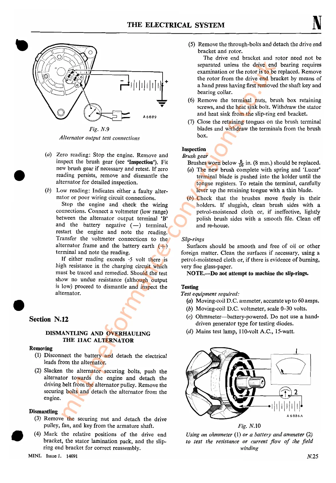
Fig. N.IO
Using an ohmmeter
(1) or a battery
and
ammeter (2)
to test the resistance or current flow
of
the field
winding
N.25
mk1-performance-conversions.co.uk
 Loading...


