THE
ELECTRICAL SYSTEM
~~
17
16
N
24
23
6
7
/
/
/
/
/
18
IS'
E0625
•
•
1.
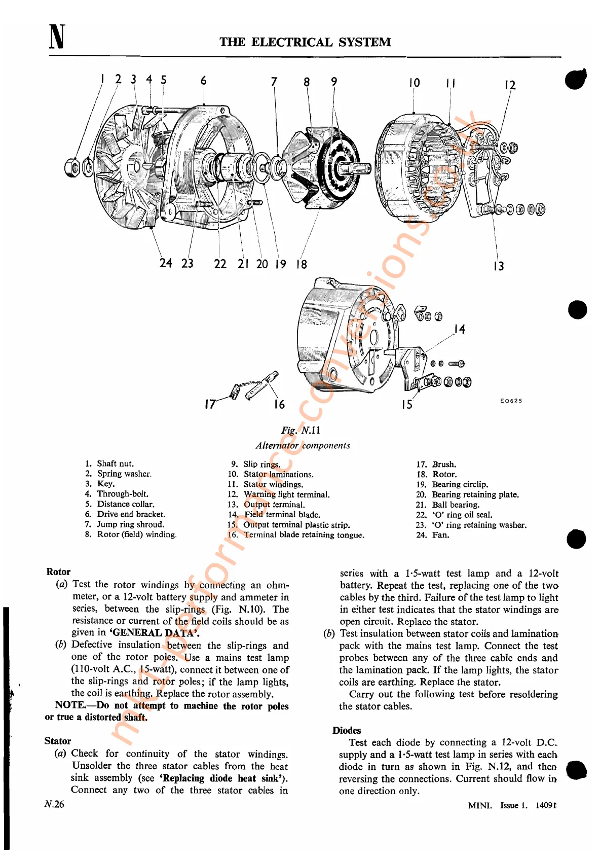
Shaft nut.
2. Spring washer.
3. Key.
4. Through-bolt.
5.
Distance collar.
6. Drive end bracket.
7. Jump ring shroud.
8.
Rotor
(field) winding.
Fig.
N.ll
Alternator components
9. Slip rings.
10. Stator laminations.
11.
Stator windings.
12.
Warning light terminal.
13.
Output terminal.
14.
Field terminal blade.
15.
Output terminal plastic strip.
16.
Terminal blade retaining tongue.
17. Brush.
18. Rotor.
19. Bearing circlip.
20. Bearing retaining plate.
21. Ball bearing.
22.
'0'
ring oil seal.
23.
'0'
ring retaining washer.
24.
Fan.
•
Rotor
(a)
Test the rotor windings
by
connecting
an
ohm-
meter, or a 12-volt battery supply and ammeter in
series, between the slip-rings (Fig. N.IO). The
resistance or current
of
the field coils should be as
given in 'GENERAL DATA'.
(b) Defective insulation between the slip-rings and
one
of
the rotor poles. Use a mains test lamp
(llO-volt A.C., IS-watt), connect it between one
of
the slip-rings and rotor poles;
if
the lamp lights,
the coil
is
earthing. Replace the rotor assembly.
NOTE.-Do
not attempt to machine the rotor poles
or true a distorted shaft.
Stator
(a) Check for continuity
of
the stator windings.
Unsolder the three stator cables from the heat
sink assembly (see 'Replacing diode heat sink').
Connect any two
of
the three stator cables in
N.26
series with a I·S-watt test lamp and a 12-volt
battery. Repeat the test, replacing one
of
the two
cables by the third. Failure
of
the test lamp to light
in either test indicates that the stator windings
are
open circuit. Replace the stator.
(b) Test insulation between stator coils and lamination
pack with the mains test lamp. Connect the test
probes between any
of
the three cable ends and
the lamination pack.
If
the lamp lights, the
stator
coils are earthing. Replace the stator.
Carry out the following test before resoldering
the stator cables.
Diodes
Test each diode by connecting a 12-volt
D.CL
supply and a I·S-watt test lamp in series with each
diode in turn as shown in Fig. N·
h
I2,
ladnfld
th~n
.'
reversing the connections. Current s ou ow In
one direction only.
MINI. Issue
1.
1409.11
mk1-performance-conversions.co.uk
 Loading...


