THE
ELECTRICAL SYSTEM
•
•
11
III
Fig. N.12
Testing the diodes
00389
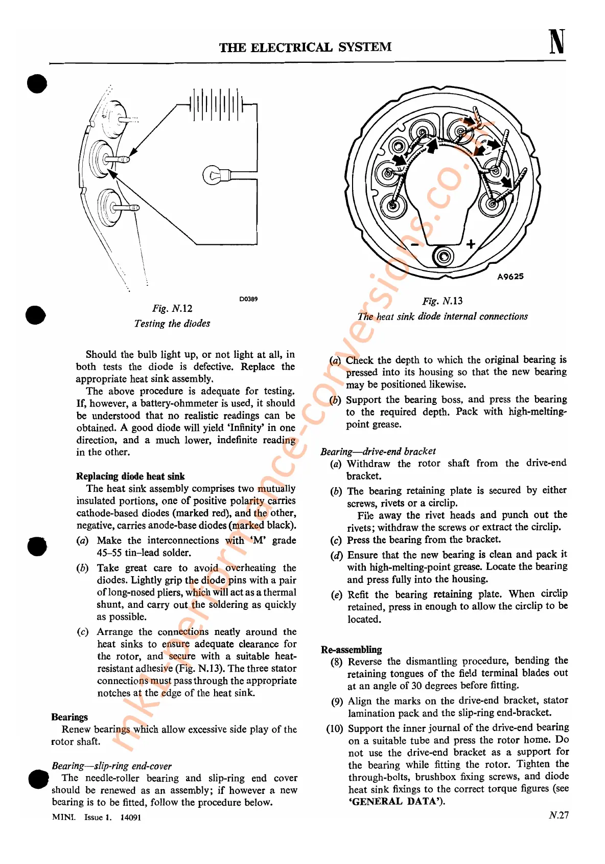
Fig. N.13
The heat sink diode internal connections
N
Bearings
Renew bearings which allow excessive side play
of
the
rotor shaft.
Bearing-slip-ring end-cover
• The needle-roller bearing and slip-ring end cover
should
be
renewed as an assembly;
if
however a new
bearing
is
to
be
fitted, follow the procedure below.
MINI. Issue
1.
14091
.'
Should the bulb light up,
or
not light
at
all, in
both tests the diode
is
defective. Replace the
appropriate heat sink assembly.
The above procedure
is
adequate for testing.
If,
however, a battery-ohmmeter
is
used, it should
be understood that no realistic readings can be
obtained. A good diode will yield 'Infinity' in one
direction, and a much lower, indefinite reading
in the other.
Replacing diode
heat
sink
The heat sink assembly comprises two mutually
insulated portions, one
of
positive polarity carries
cathode-based diodes (marked red), and the other,
negative, carries anode-base diodes (marked black).
(a) Make the interconnections with
'M'
grade
45-55 tin-lead solder.
(b) Take great care
to
avoid overheating the
diodes. Lightly grip the diode pins with a pair
of
long-nosed pliers, which
will
actas a thermal
shunt, and carry out the soldering as quickly
as possible.
(c) Arrange the connections neatly around the
heat sinks to ensure adequate clearance for
the rotor, and secure with a suitable heat-
resistant adhesive (Fig. N.13). The three stator
connections must pass through the appropriate
notches
at
the edge
of
the heat sink.
(a) Check the depth to which the original bearing is
pressed into its housing so that the new bearing
may be positioned likewise.
(b) Support the bearing boss, and press the bearing
to the required depth. Pack with high-melting-
point grease.
Bearing-drive-end bracket
(a) Withdraw the rotor shaft from the drive-end
bracket.
(b) The bearing retaining plate is secured by either
screws, rivets
or
a circlip.
File away the rivet heads and punch
out
the
rivets; withdraw the screws
or
extract the circlip.
(c) Press the bearing from the bracket.
(d) Ensure that the new bearing is clean and pack it
with high-melting-point grease. Locate the bearing
and press fully into the housing.
(e)
Refit the bearing retaining plate. When circlip
retained, press in enough to allow the circlip to be
located.
Re-assembling
(8)
Reverse the dismantling procedure, bending the
retaining tongues
of
the field terminal blades out
at
an angle
of
30
degrees before fitting.
(9)
Align the marks
on
the drive-end bracket, stator
lamination pack and the slip-ring end-bracket.
(10)
Support the inner journal
of
the drive-end bearing
on
a suitable tube and press the rotor home.
Do
not
use the drive-end bracket as a support for
the bearing while fitting the rotor. Tighten the
through-bolts, brushbox fixing screws, and diode
heat sink fixings to the correct torque figures (see
'GENERAL DATA').
N.27
mk1-performance-conversions.co.uk
 Loading...


