00717
N
THE
ELECTRICAL SYSTEM
,---
N
n____
_ _
I
'-
N /
I~
·
~J
~I~~®
N7l
~N
NP~
I I
N8.
0~J
CD
r---
N
-,
I
AL_I_
1:+
NY
yWL
L
AI--
PJ
w---@-rvb.Q"IU
D
~
ri]~4
*8:-~1:
I
-t
@
o
G~
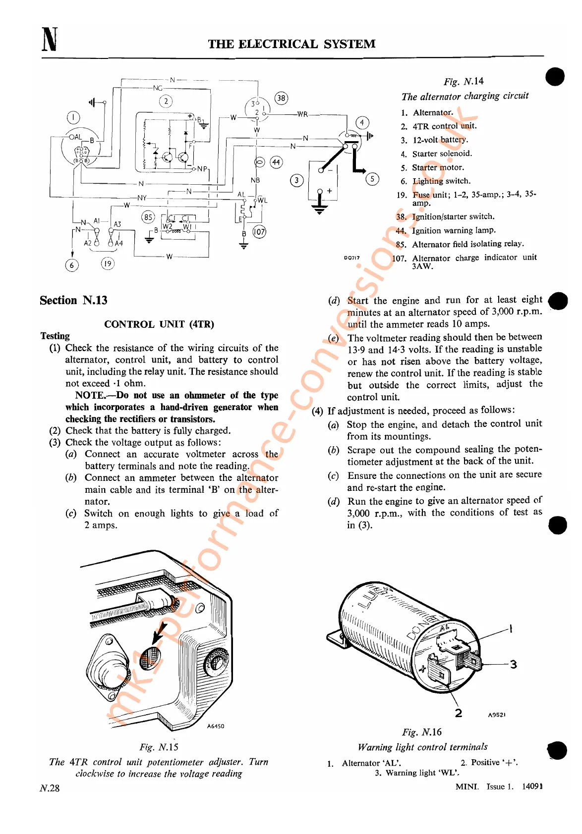
Fig.
N.I4
The alternator charging circuit
1.
Alternator.
2.
4TR
control unit.
3.
12-volt battery.
4.
Starter solenoid.
5.
Starter motor.
6. Lighting switch.
19. Fuse unit; 1-2, 35-amp.; 3-4, 35-
amp.
38. Ignition/starter switch.
44. Ignition warning lamp.
85. Alternator field isolating relay.
107. Alternator charge indicator unit
3AW.
•
Section N.13
CONTROL UNIT (4TR)
Testing
(1) Check the resistance
of
the wiring circuits
of
the
alternator, control unit, and battery to control
unit, including the relay unit. The resistance should
not exceed
·1
ohm.
NOTE.-Do
Dot
use an ohmmeter
of
the type
which
incorporates a hand-driven generator
when
checking the rectifiers or transistors.
(2) Check that the battery
is
fully charged.
(3) Check the voltage output as follows:
(a) Connect
an
accurate voltmeter across the
battery terminals and note the reading.
(b) Connect
an
ammeter between the alternator
main cable and its terminal
'B'
on the alter-
nator.
(c) Switch on enough lights to give a load
of
2 amps.
(d) Start the engine
and
run for
at
least eight •
minutes at
an
alternator speed
of
3,000 r.p.m. -
until the ammeter reads 10 amps.
(e) The voltmeter reading should then be between
13·9 and 14·3 volts.
If
the reading is unstable
or
has
not
risen above the battery voltage,
renew the control unit.
If
the reading
is
stable
but outside the correct limits, adjust
the
control unit.
(4)
If
adjustment is needed, proceed as follows:
(a) Stop the engine, and detach the control unit
from its mountings.
(b) Scrape
out
the compound sealing the poten-
tiometer adjustment
at
the back
of
the unit.
(c) Ensure the connections
on
the unit are secure
and re-start the engine.
(d)
Run
the engine to give
an
alternator speed
of
3,000 r.p.m., with the conditions
of
test as
in (3). •
•
~1'---3
2 A9521
Fig.
N.I6
Warning light control terminals
1.
Alternator
'AL'.
2. Positive '+'.
3.
Warning light oWL'.
MINI.
Issue 1. 1409)
Fig. N.15
The
4TR
control unit potentiometer adjuster. Turn
clockwise to increase the voltage reading
N.28
mk1-performance-conversions.co.uk
 Loading...


