R
THE BODY
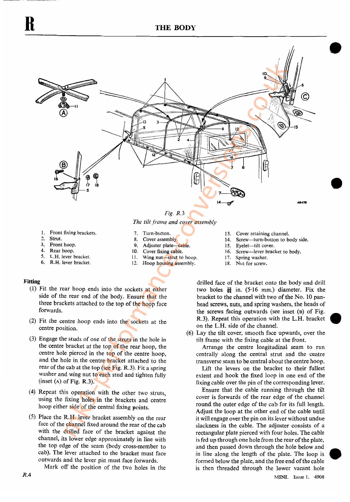
Fig.
R.3
The tilt fj'ame and cover assembly
•
•
1.
Front fixing brackets.
2.
Strut.
3.
Front
hoop.
4.
Rear hoop.
5.
L.H. lever bracket.
6.
R.H. lever bracket.
7.
Turn-button.
8.
Cover assembly.
9.
Adjuster
plate-cable.
10.
Cover fixing cable.
11.
Wing
nut-strut
to hoop.
12.
Hoop housing assembly.
13.
Cover retaining channel.
14.
Screw-turn-botton
to
body side.
15.
Eyelet-tilt
cover.
16.
Screw-lever
bracket to body.
17.
Spring washer.
18.
Nut
for screw.
Fitting
(1)
Fit
the rear hoop ends into the sockets at either
side
of
the rear end
of
the body. Ensure that the
three brackets attached to the top
of
the hoop face
forwards.
(2)
Fit the centre hoop ends into the sockets at the
centre position.
(3)
Engage the studs
of
one
of
the struts in the hole in
the centre bracket
at
the top
of
the rear hoop, the
centre hole pierced in the top
of
the centre hoop,
and the hole in the centre bracket attached to the
rear
of
the cab
at
the top (see Fig. R.3). Fit a spring
washer and wing nut to each stud and tighten fully
(inset
(A)
of
Fig. R.3).
(4)
Repeat this operation with the other two struts,
using the fixing holes in the brackets and centre
hoop either side
of
the central fixing points.
(5)
Place the R.H. lever bracket assembly on the rear
face
of
the channel fixed around the rear
of
the cab
with the drilled face
of
the bracket against the
channel, its lower edge approximately in line with
the top edge
of
the seam (body cross-member to
cab). The lever attached to the bracket must face
outwards and the lever pin must face forwards.
Mark off the position
of
the two holes in the
RA
drilled face
of
the bracket onto the body and drill
two holes
H in. (5,16 mm.) diameter. Fix the
bracket to the channel with two
of
the No.
10
pan-
head screws, nuts, and spring washers, the heads
of
the screws facing outwards (see inset
CB)
of
Fig.
R.3). Repeat this operation with the L.H. bracket •
on the L.H. side
of
the channel.
(6)
Lay the tilt cover, smooth face upwards, over the
tilt frame with the fixing cable
at
the front.
Arrange the centre longitudinal seam to run
centrally along the central strut and the centre
transverse seamto be central about the centre hoop.
Lift the levers on the bracket to their fullest
extent and hook the fixed loop in one end
of
the
fixing cable over the pin
of
the corresponding lever.
Ensure that the cable running through the tilt
cover is forwards
of
the rear edge
of
the channel
round the outer edge
of
the cab for its full length.
Adjust the loop
at
the other end
of
the cable until
it will engage over the pin
on
its lever withoutundue
slackness in the cable. The adjuster consists
of
a
rectangular plate pierced with four holes. The cable
is
fed upthrough one hole from the rear
of
theplate,
and then passed down through the hole below and
in line along the length
of
the plate. The loop
is
•
formed below the plate, andthe free end
of
the cable
is
then threaded through the
l(!)wer
vacant hole
MINI. Issue
1.
4908
mk1-performance-conversions.co.uk