THE
FUEL SYSTEM
D
• Section D.3
•
•
•
FUEL
PUMP-TYPE
PD
Apart from cleaning the filter and contact points
t
no
servicing
is
possible; ifthe pump fails a new one must be
fitted.
Removing
(1)
Disconnect the leads, slacken the clamp screws,
and pull off the fuel pipes. Unscrew the bracket
screws and remove the pump and bracket.
Cleaning the filter
(2)
Remove the pump and take off the bottom cover
plate. Extract the filter and clean it with a brush
and petrol (fuel). Fit a new cover gasket.
Points
(3)
Lift, off the top cover and clean the points by
drawing a piece
of
clean paper between them.
(4)
Check that the points make good contact and that
the gap between the end
of
the upper blade and its
stop face
is
not less than
·015
in. (,4 mm.).
Refitting
(5)
Reverse the removing instructions.
Section D.4
FUEL
PUMP-TYPE
SP
AND AUF
201
The pump is mounted on the lower left-hand flange
of
the rear sub-frame.
Removing
(1)
Disconnect the batterYt the pump leads, and both
hoses.
(2)
Unscrew the nut securing the pump clamp to the
bracket and lift off the pump and clamp.
Refitting
(3)
Reverse the removing instructions.
Dismantling
(4)
Screw the inlet nozzle from the pump body and
withdraw the filter and fibre washer.
(
5)
Unscrew the six screws securing the coil housing
to the body, separate the housing, diaphragm, and
body.
(6)
Withdraw the retainer screw, retainer, and valves.
(7)
Unscrew the armature from the inner rocker
trunnion and remove the brass rollers, feed spring
and impact washer from the armature.
(8)
Remove the terminal nut, Lucar connector and
washer from the terminal screw and take off the
bakelite cap.
MINI.
Issue
1.
4908
~,.
/5144
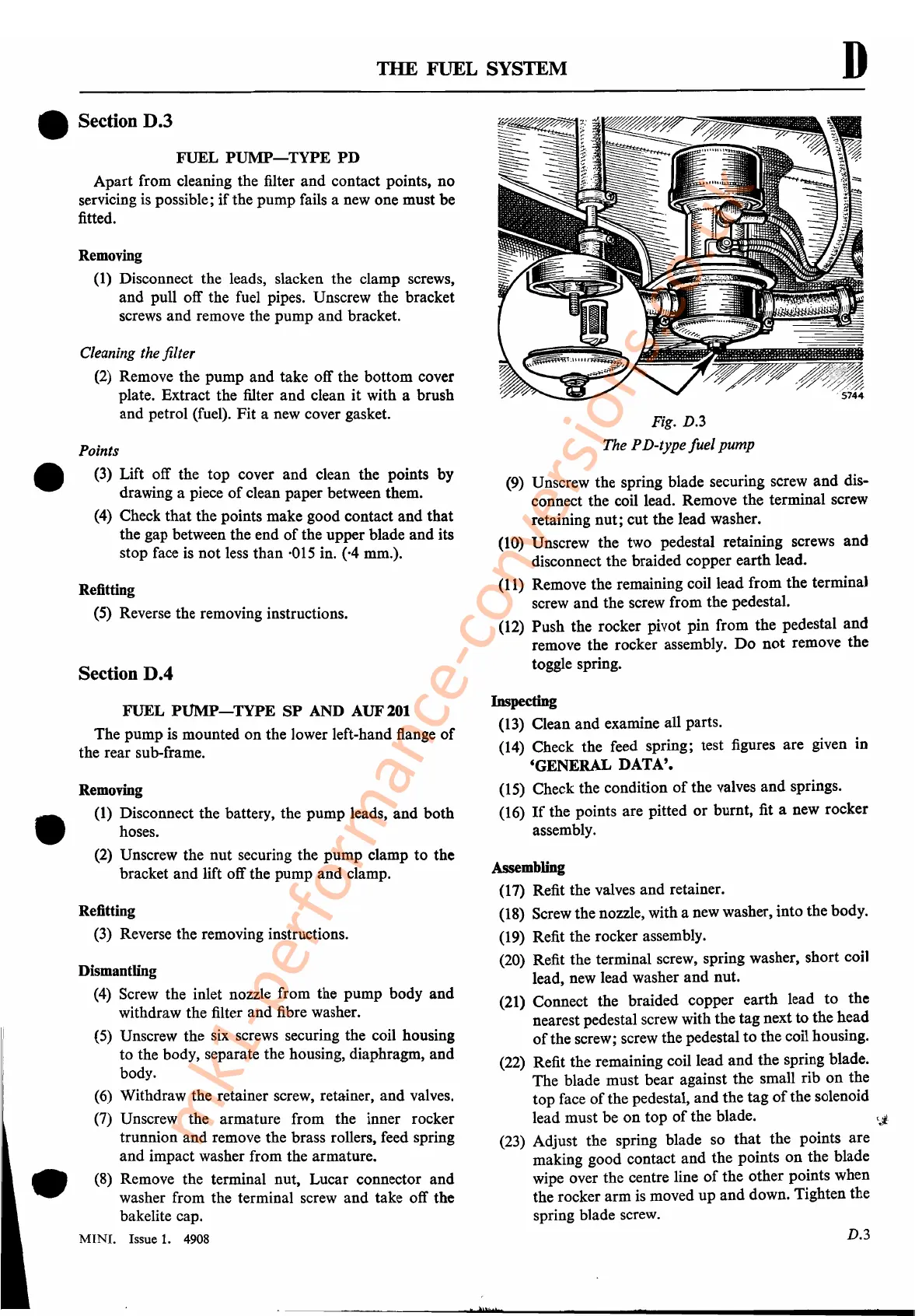
Fig. D.3
The
PD-type
fuel
pump
(9)
Unscrew the spring blade securing screw and dis-
connect the coil lead. Remove the terminal screw
retaining nut; cut the lead washer.
(10)
Unscrew the two pedestal retaining screws and
disconnect the braided copper earth lead.
(11)
Remove the remaining coil lead from the terminal
screw and the screw from the pedestal.
(12)
Push the rocker pivot pin from the pedestal and
remove the rocker assembly.
Do
not remove the
toggle spring.
Inspecting
(13)
Clean and examine all parts.
(14)
Check the feed spring; test figures are given in
'GENERAL
DATA'.
(15)
Check the condition
of
the valves and springs.
(16)
If
the points are pitted or burnt, fit a new rocker
assembly.
Assembling
(17)
Refit the valves and retainer.
(18)
Screw the nozzle, with a new washer, into the body.
(19)
Refit the rocker assembly.
(20)
Refit the terminal screw, spring washer, short coil
lead, new lead washer and nut.
(21)
Connect the braided copper earth lead to the
nearest pedestal screw with the tag next
to
the head '
of
the screw; screw the pedestal to the coil housing.
(22)
Refit the remaining coil lead and the spring blade.
The blade must bear against the small rib on the
top face
of
the pedestal, and the tag
of
the solenoid
lead must be on top
of
the blade.
(23)
Adjust the spring blade so that the points are
making good contact and the points on the blade
wipe over the centre line
of
the other points when
the rocker arm
is
moved up and down. Tighten the
spring blade screw.
D.3
t'
Mt-
i
mk1-performance-conversions.co.uk