THE
FUEL SYSTEM
D
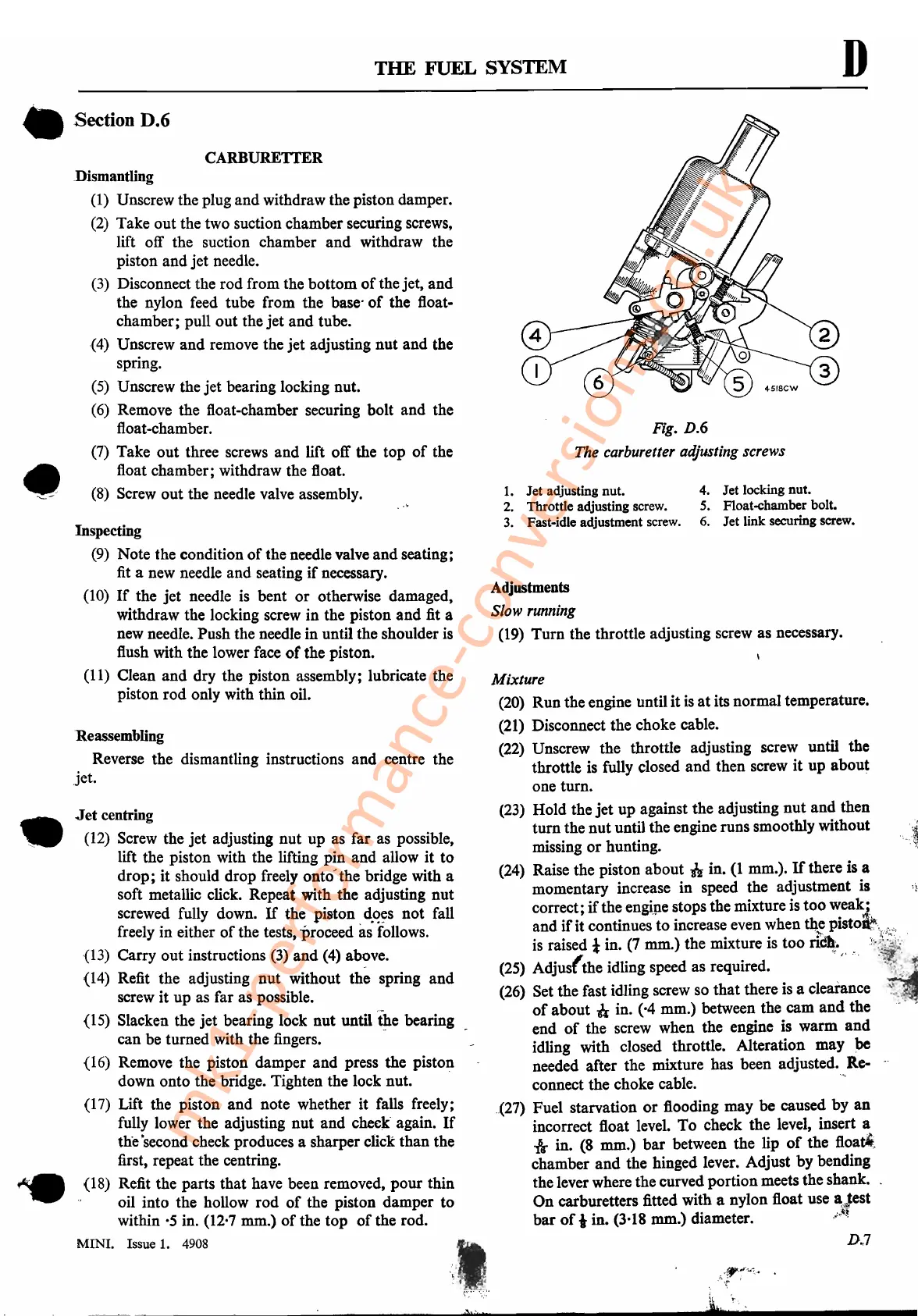
4. Jet locking
nut.
5. Float-chamber bolt.
6.
Jet link securing screw.
1.
Jet adjusting nut.
2. Throttle adjusting screw.
3.
Fast-idle adjustment screw.
I,f,'r---"
\,
'"
':
'
'M
Fig. D.6
The carburetter adjusting screws
Mixture
(20) Run the engine until
it
is
at
its normal temperature.
(21) Disconnect the choke cable.
(22) Unscrew the throttle adjusting screw until the
throttle is fully closed
and
then screw
it
up about
one turn.
(23) Hold the
jet
up against the adjusting
nut
and then
turn the nut until the engine runs smoothly without
missing
or
hunting.
(24) Raise the piston about
if
in.
(1
mm.).
If
there is a
momentary increase in speed the adjustment is
correct;
if
the engipe stops the mixture is
too
weak""
and
if
it continues to increase even when
th.e
pist01\~"c;,,,
is
raised 1in. (7 mm.) the mixture is too
ri~.
:~{~<"'\
(25) Adjus(the idling speed as required. .
(26) Set the fast idling screw so that there is a clearance
of
about n in. ('4 mm.) between the cam
and
the
end
of
the screw when the engine is warm
and
idling with closed throttle. Alteration may
pe
needed after the mixture has been adjusted.
R.e-
connect the choke cable.
'"
.(27) Fuel starvation
or
flooding may be caused by
an
incorrect float level.
To
check the level, insert a
*in. (8 mm.)
bar
between the lip
of
the floati,
chamber
and
the hinged lever. Adjust by bending
the lever where the curved portion meets the shank.
On
carburetters fitted with a nylon float use a:Jest
bar
of
i in. (3,18 mm.)
diameter.!l~
D.,7
Adjustments
Slow running
(19)
Turn the throttle adjusting screw as necessary.
CARBURETTER
Inspecting
(9)
Note the condition
of
the needle valve and seating;
fit a new needle and seating
if
necessary.
(10)
If
the
jet
needle is bent
or
otherwise
damaged~
withdraw the locking screw in the piston and fit a
new needle. Push the needle in until the shoulder
is
flush with the lower face
of
the piston.
(11) Clean
and
dry the piston assembly; lubricate the
piston
rod
only with thin oil.
Jet
centring
(12)
Screw the
jet
adjusting
nut
up as far as possible,
lift the piston with the lifting pin and allow
it
to
drop;
it
should drop freely onto
J
the bridge with a
soft metallic click. Repeat with the adjusting
nut
screwed fully down.
If
the. piston.
d.,?~s
not fall
freely in either
of
the tests, 'proceed as follows.
(13) Carry out instructions (3) and (4) above.
(14) Refit the adjusting nut without the spring and
screw it up as far as possible.
(IS) Slacken the
jet
bearing lock nut untiltl.te bearing
can be turned with the fingers.
(16) Remove the piston damper and press the piston
down onto the bridge. Tighten the lock nut.
(17) Lift the piston
and
note whether it falls freely;
fully lower the adjusting nut
and
check again.
If
th'e
'second check produces a sharper click than the
first, repeat the centring.
(18) Refit the parts that have been removed,
pour
thin
oil into the hollow
rod
of
the piston damper to
within
'5
in. (12'7 mm.)
of
the top
of
the rod.
MINI.
Issue 1. 4908
Dismantling
(1)
Unscrew the plug
and
withdraw the piston damper.
(2) Take out the two suction chamber securing screws,
lift off the suction chamber
and
withdraw the
piston and jet needle.
(3) Disconnect the rod from the bottom
of
the jet,
and
the nylon feed tube from the base·
of
the float-
chamber; pull out the
jet
and tube.
(4) Unscrew and remove the jet adjusting nut and the
spring.
(5) Unscrew the
jet
bearing locking nut.
(6) Remove the float-chamber securing bolt and the
float-chamber.
(7) Take out three screws and lift off the top
of
the
float chamber; withdraw the float.
(8) Screw out the needle valve assembly.
Reassembling
Reverse the dismantling instructions and centre the
jet.
• Section D.6
•
'---
•
mk1-performance-conversions.co.uk