F
THE
TRANSMISSION
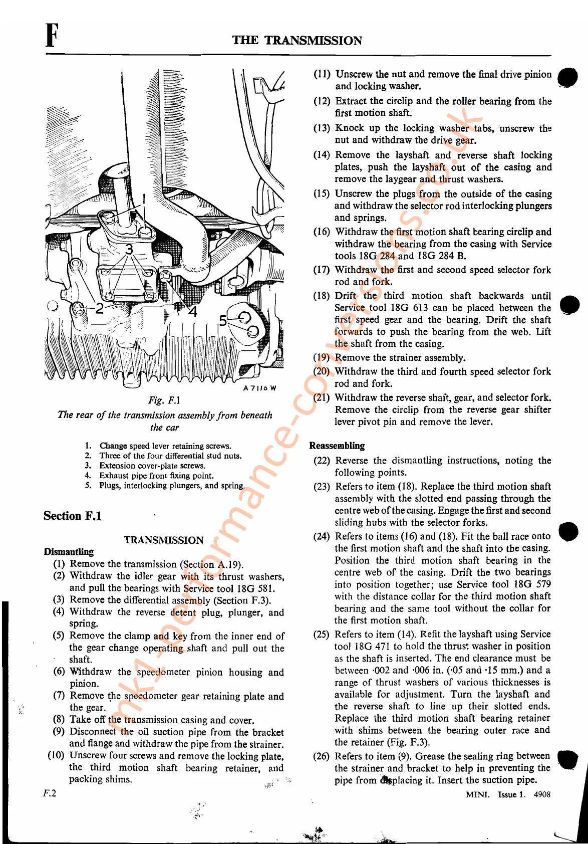
Fig.
F.l
The rear
of
the transmission assembly from beneath
the car
1.
Change speed lever retaining screws.
2. Three
of
the four differential stud nuts.
3.
Extension cover-plate screws.
4. Exhaust pipe front fixing point.
5.
Plugs, interlocking plungers, and spring.
Section F.1
TRANSl\lISSION
Dismantling
(1)
Remove the transmission (Section A.l9).
(2)
Withdraw the idler gear with its thrust washers,
and pull the bearings with Service tool
180
581.
(3)
Remove the differential assembly (Section F.3).
(4)
Withdraw the reverse detent plug, plunger, and
spring.
(5)
Remove the clamp and key from the inner end
of
the gear change operating shaft and pull out the
shaft.
(6)
Withdraw the speedometer pinion housing and
pinion.
(7)
Remove
~he
speedometer gear retaining plate and
the gear.
(8)
Take off the transmission casing and cover.
(9) Disconnect the oil suction pipe from the bracket
and flange and withdraw the pipe from the strainer.
(10)
Unscrew four screws and remove the locking plate,
the third motion shaft bearing retainer, and
packing shims.
F.2
(11) Unscrew the nut and remove the final drive
Pinion.
and locking washer.
(12)
Extract the circlip and the roller bearing from the
first motion shaft.
(13)
Knock up the locking washer tabs, unscrew the
nut and withdraw the drive gear.
(14)
Remove the layshaft and reverse shaft locking
plates, push the layshaft out
of
the casing and
remove the laygear and thrust washers.
(
15)
Unscrew the plugs from the outside
of
the casing
and withdraw the selector rod interlocking plungers
and springs.
(16) Withdraw the first motion shaft bearing circlip and
withdraw the bearing from the casing with Service
tools
180284
and
180284
B.
(17)
Withdraw the first and second speed selector fork
rod and fork.
(18) Drift the third motion shaft backwards until
Service tool
180
613
can be placed between the •
first speed gear and the. bearing. Drift the shaft
forwards to push the bearing from the web. Lift
the shaft from the casing.
(19)
Remove the strainer assembly.
(20)
Withdraw the third and fourth speed selector fork
rod and fork.
(21)
Withdraw the reverse shaft, gear, and selector fork.
Remove the circlip from the reverse gear shifter
lever pivot pin and remove the lever.
Reassembling
(22)
Reverse the dismantling instructions, noting the
following points.
(23)
Refers to item (18). Replace the third motion shaft
assembly with the slotted end passing through the
centre web
of
the casing. Engage thefirst and second
sliding hubs with the selector forks.
(24)
Refers to items
(16)
and (18). Fit the ball race onto •
the first motion shaft and the shaft into the casing.
Position the third motion shaft bearing in the
centre
web
of
the casing. Drift the two bearings
into position together; use Service tool
180
579
with the distance collar for the third motion shaft
bearing and the same tool without the collar for
the first motion shaft.
(25)
Refers to item (14). Refit the layshaft using Service
tool
180471
to hold the thrust washer in position
as the shaft
is
inserted. The end clearance must be
between
·002
and ·006 in. (,05 and
·15
mm.) and a
range
of
thrust washers
of
various thicknesses
is
available for adjustment. Turn the layshaft and
the reverse shaft to line up their slotted ends.
Replace the third motion shaft bearing retainer
with shims between the bearing outer race and
the retainer (Fig. F.3).
(26)
Rhefers
t?
item
d(9)b'
Orkease
thhe
slealin
g
ring
b~tweehn
-
•..
t e stramer an rac et to e p in preventmg t e -
pipe from dtJplacing it. Insert the suction pipe.
MINI. Issue
1.
4908
mk1-performance-conversions.co.uk