44 en | Installation material and tools DICENTIS
2021.01 | V2.2 |
Hardware Installation Manual
Bosch Security Systems B.V.
3 Screw holes Used to mount the device on a flat surface
4 Cable tie recess Used to secure the device, preventing side movement
Mounting
To secure the DCNM-IDESKINT to a flat surface, insert two 2.5 mm screws in the existing holes
on the flaps (3). You can also fix the DCNM-IDESKINT by wrapping a cable tie around the
device using the existing recess (4) to prevent side movement.
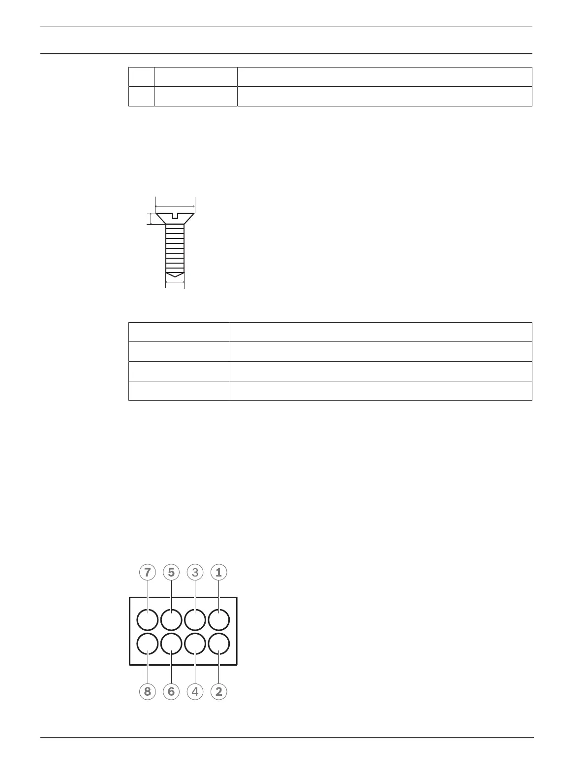
Figure5.13: Screw max dimensions
Flat head
A 8mm
B 2mm
C 2.5mm
Connection
USB-B to USB-A
The interface is connected to the USB-A port of one of the DCNM-IDESK devices inside the
interpreter’s booth. The maximum length of the USB cable is 5m.
Note: the USB cable must be purchased separately.
8-pin Phoenix connector
The 8-pin Phoenix connector interfaces with the external telephone system and booth on-air
LED. The input of the connector is used for the external telephone system, while the output is
used for the external booth on-air LED. See the image and table below for reference.
Figure5.14: 8-pin Phoenix connector