DICENTIS Installation material and tools | en 45
Bosch Security Systems B.V.
Hardware Installation Manual
2021.01 | V2.2 |
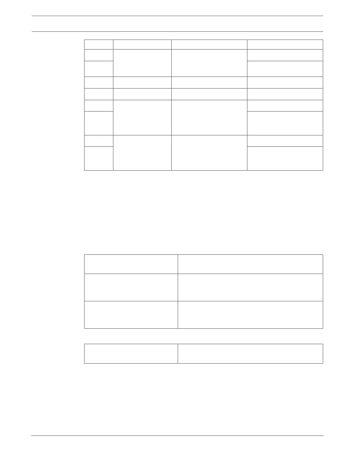
Pin # Function Specifications Description
1 Switch to set the
booth on-air LED on/
off
50V/1A potential free
contact
Galvanic separated
OUTPUT
2 OUTPUT
3
4
5 Input for an external
telephone system
ringing indicator
inactive: < 1VDC
active: > 3VDC
max.: 24VDC
Galvanic separated
INPUT Negative ( - )
6 INPUT Positive ( + )
7 Input for an external
system for warning
indicator
inactive: < 1VDC
active: > 3VDC
max.: 24VDC
Galvanic separated
INPUT Negative ( - )
8 INPUT Positive ( + )
Tab.5.8: Connector pinout
Note: the female plug to be used with the 8-pin connector is supplied pre-assembled with the
product. You will need to make the wire connections, which only require simple push-in action
to lock.
Wiring
The connection to the Phoenix connector has to be made using ferrules.
The tables below give more details on the connection.
Conductor cross section max.
(solid and flexible)
1.5mm
2
Conductor cross section flexible,
with ferrule without plastic sleeve
max.
1.5mm
2
Conductor cross section flexible,
with ferrule with plastic sleeve
max.
0.75mm
2
Tab.5.9: Connection data
Ferrules without insulating collar
(according to DIN46228-1)
Cross section: 0.22mm
2
to 1.5mm
2
Length: 5mm to 10mm
Tab.5.10: Specifications for ferrules