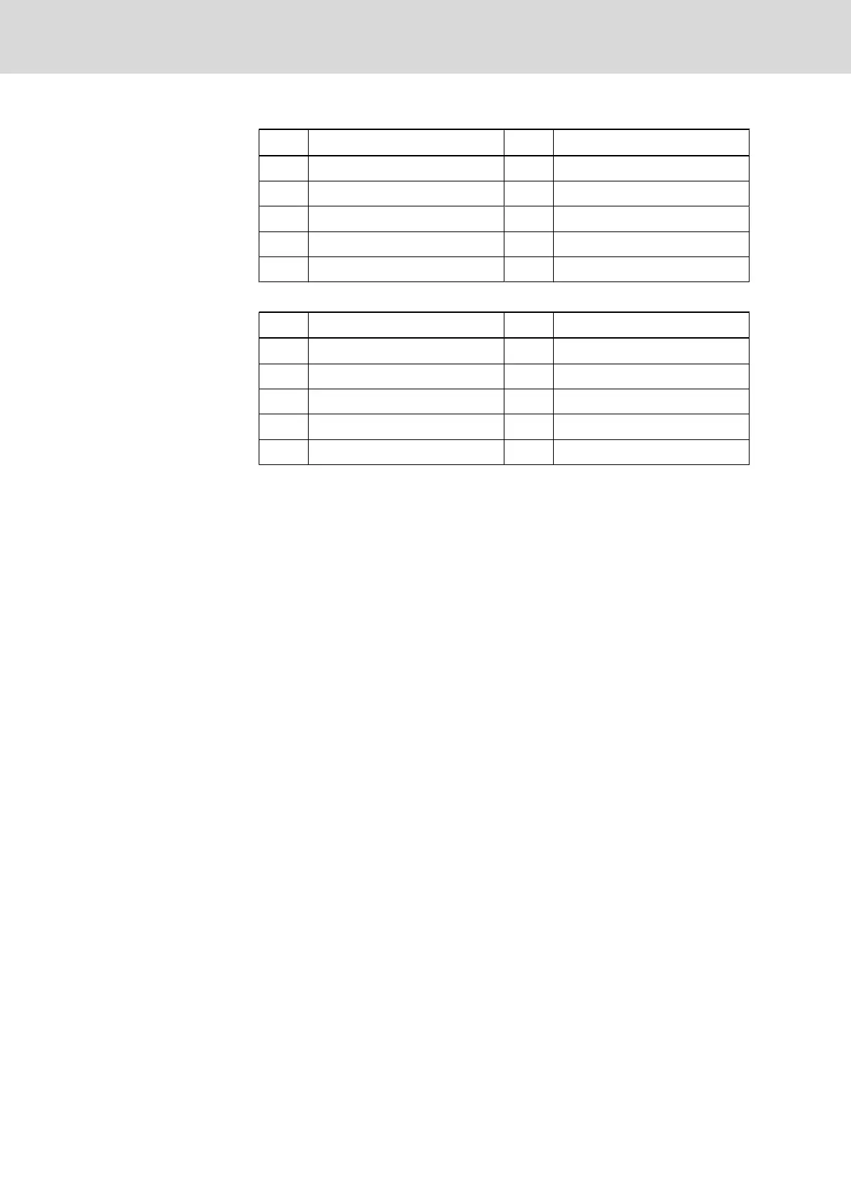
PIN Signal designation PIN Signal designation
1 NC 2 RxD - Receive Data
3 TxD - Transmit Data 4 DTR - Data Terminal Ready
5 GND - Signal ground 6 NC
7 RTS - Ready To Send 8 CTS - Clear To Send
9 NC
Fig.9-25: Pin assignment diagnosis interface RS232C (X74, X79)
PIN Signal designation PIN Signal designation
1 RGND - Reference potential 2 NC
3 RxD/TxD-P - Send/Receive 4 NC
5 DGND - Reference potential 6 VP - Supply voltage - Plus
7 NC 8 RxD/TxD-N - Send/Receive
9 NC
Fig.9-26: Pin assignment PROFIBUS interface (X70, X75)
9.7 Connecting the Hand-held terminal BTC 06
The hand-held terminal BTC 06 may only and exclusively be connected via the
machine operator panels BTA 10 or BTA 20. RS232 operation is converted into
RS422 operation by the interface converter integrated in the BTA 10/20 (see
fig. 9-27 "MTS-P with BTC 06 via RS232 interface" on page 125). RS422 op‐
eration with BTC 06 also is only possible via BTA 10/20. However, no interface
conversion takes place in this case. The interface connector is merely adapted
to the BTC 06 connector (see fig. 9-28 "MTS-P with BTC 06 via RS422 inter‐
face" on page 126).
124/135 Bosch Rexroth AG | Electric Drives
and Controls
Rexroth MTA 200 | Project Planning Manual
PLC Modules MTS-P01.2 and MTS-P02.2

 Loading...


