1 695 600 091 2012-11-16| Robert Bosch GmbH
Operation | WBE 4200 | 39 en
4. Operation
i After switching on the WBE 4200 the software
version appears on the displays of the control/
display panel for a few seconds. The 0 values are
then shown on the left and right of the display.
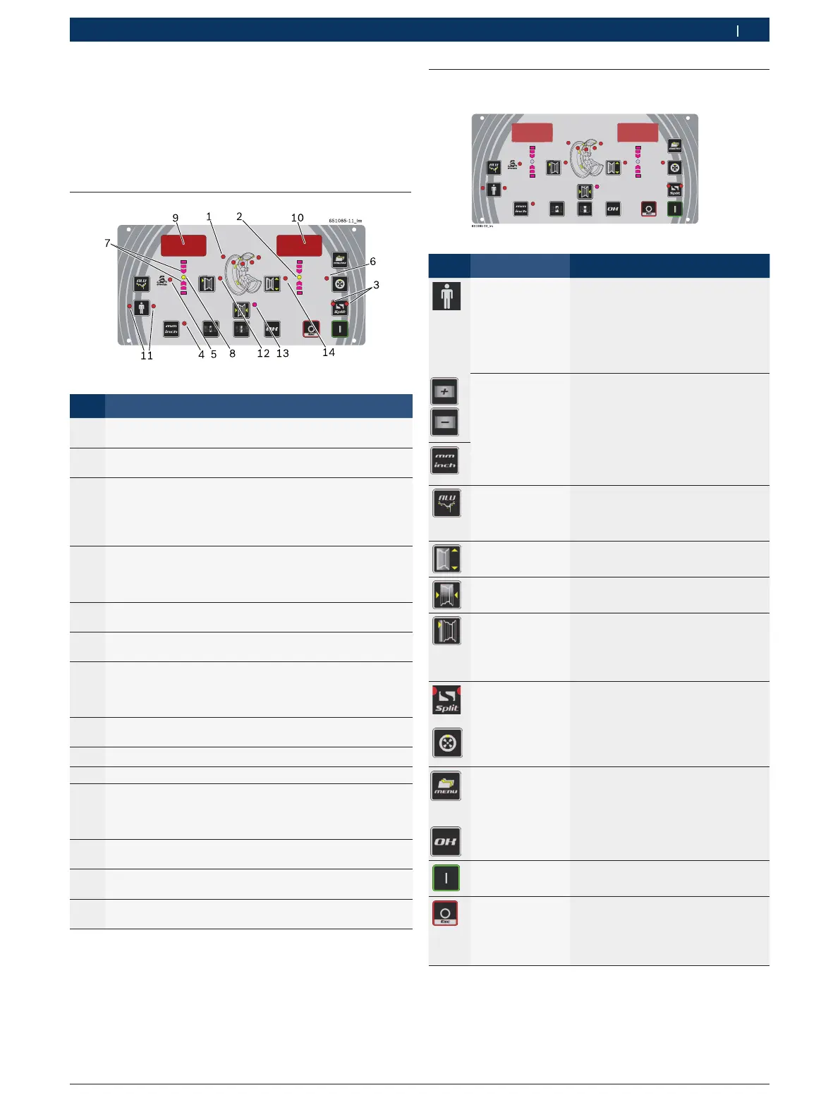
4.1 Display
Fig. 2: Display elements
Item Description
1 Displays the active (selected) balancing program and
balancing positions (see sections 9.1).
2 Indication of external weight balancing point; it lights-up
green when the balancing position is reached.
3 Split and Matching program display
- During the Split program, the LEDs flash alternately in
accordance with the weight position
- During the Matching program, both LEDs light
simultaneously
4 Displays the unit of measurement for the rim width and
rim diameter,
lit = mm,
not lit = inch.
5 Displays the balancing program,
lights up when Pax program is selected.
6 Displays the Match program, lights up when Match
program is active.
7 Displays the direction of rotation to reach the balancing
position,
top = turn clockwise,
bottom = turn anti-clockwise.
8 Indication of internal weight balancing point; it lights-up
green when the balancing position is reached.
9 Internal weight display.
10 External weight display.
11 Display of active or selected operator:
Left LED: OPERATOR 1
Right LED: OPERATOR 2
Both LEDs: OPERATOR 3
12 LED lit: Rim distance data are displayed or can be
entered.
13 LED lit: Rim width data are displayed or can be entered.
14 LED lit: Rim diameter data are displayed or can be
entered.
Tab. 1:
4.2 Control keys
Fig. 3:
Key Designation Description
<OPERATOR>
R Change of operator,
R call-up of basic settings (in
conjunction with menu key, refer
to Section 8)
R Call-up of calibration (in
conjunction with menu key, refer
to Section 8)
<+>
<->
R Alteration of values
R Alteration of settings
+ = "On",
– = "Off".
R Selection of balancing program
<mm/inch>
If LED is on it indicates the
measurement unit is in mm; vice-
versa, it is in inch.
<ALU>
R Call-up of balancing program,
selection with <-> or <+>,
R selection of vehicle type (1
second).
<RIM
DIAMETER
>
R Rim diameter display.
<RIM WIDTH>
R Rim width display,
R Inch/mm unit selection.
<RIM
DISTANCE
>
R Display of rim distance from
WBE 4200.
R Confirmation of rim data input.
R Confirmation of calibration data
input
<SPLIT>
R Call-up of split program,
R end of split program,
R storage of calibration data,
<OPT> Start "Unbalance minimization"
program.
LED lit: Program activated.
<MENU>
R Call-up of user-defined settings
R Call-up of basic settings, refer to
Section 11.
R Call-up of calibration menu
<OK>
Deactivate "Attach adhesive
weights" program.
<START>
R Start: Start measurement
<STOP>
R Stop: End measurement;
R With unbalance display:
Display of exact value for
measured unbalance.
R exit from menu.
Tab. 2: