1 695 600 091 2012-11-16| Robert Bosch GmbH
54 | WBE 4200 | Adjustment interventionsen
9. Adjustment interventions
9.1 Distance potentiometer positioning
1. Remove the left side protection without
disconnecting the board;
2. start the balancing machine;
3. access the test menu;
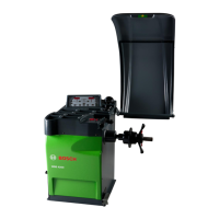
4. keeping the 4 value displayed on the board, release
the screw on the ring nut (fig.16);
Fig. 22:
5. keeping the calliper in stand-by, turn the
potentiometer using nose pliers (fig.17) to the value
of 1000 ± 50;
Fig. 23:
6. Lock the fixing screw ensuring that the upper
surface of the pinion and of the rack are complanar;
7. check the correct functioning during the run;
8. close the machine;
9. proceed with calibration of the callipers.
! The above notes are to be used for the correct
repairing; in case of replacing the entire calliper unit,
proceed only with the calibration.
9.2 Diameter potentiometer positioning
1. Remove only the carter without disconnecting the
board;
2. Start the balancing machine;
3. Enter the test menu;
4. Keep the value IN4 of the board shown;
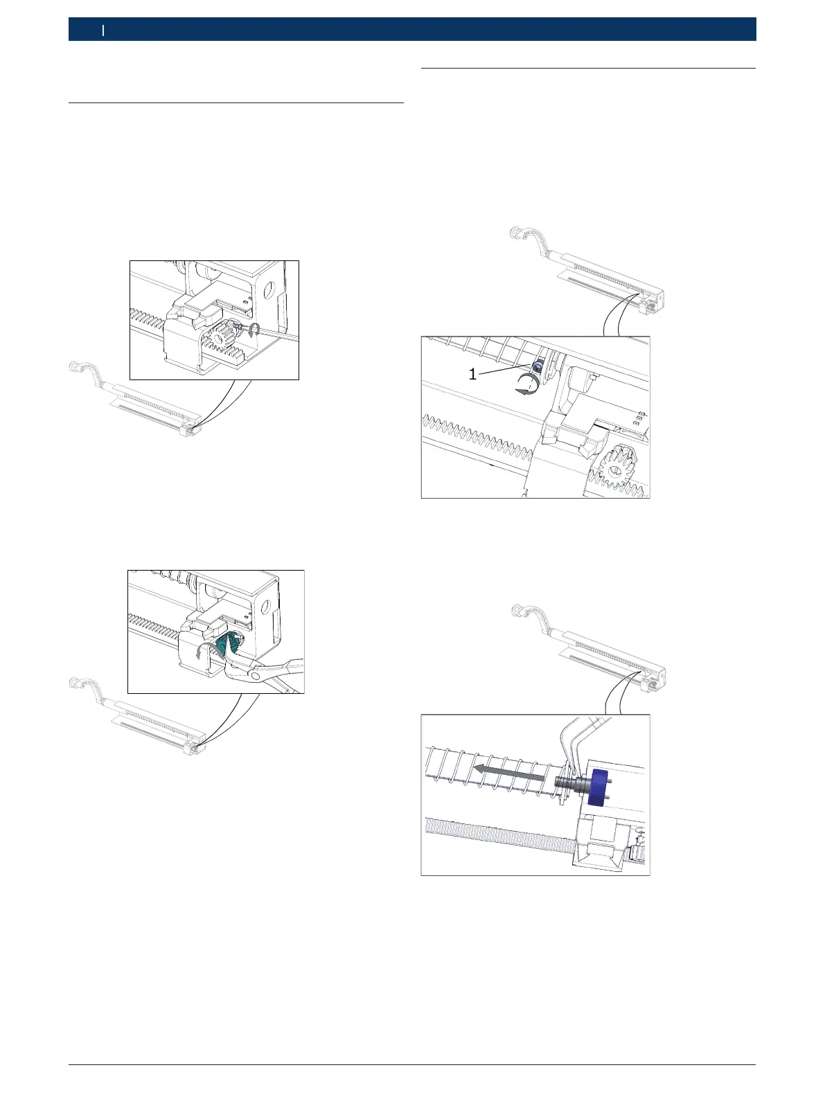
5. unblock the nut on the shaft“A” (fig.18, pos.1);
Fig. 24:
6. Slightly extract the rod of the calliper;
7. Now lean the gauge against the shaft, turn the
potentiometer “B” as far as the value of 3000 ± 50;
Fig. 25:
8. Block the nut “A” on the shaft (fig.18, pos.1);
9. Check the correct functioning during the stroke;
10. Close the machine;
11. Proceed with the calibration of gauges (chapter
Calibration menu).