1 695 600 091 2012-11-16| Robert Bosch GmbH
56 | WBE 4200 | Maintenanceen
10.4 Standard Calibration
i
As part of service and upkeep (every six months), on
flange replacement or in the event of measurement
inaccuracies, it is advisable to calibrate the
WBE 4200 in the following sequence:
1. Flange calibration.
2. Calibrating the electronic vernier caliper
3. WBE 4200 calibration.
4. Perform reference measurement.
10.4.1 Call-up of calibration menu
i Sound and automatic start are active in the following
description.
1. Press and hold the <MENU> key.
2. As soon as CAL appears on the left-hand display,
release the <MENU> key.
3. Press the <OPERATOR> key within 1.5 seconds.
"The left-hand display shows C-1.
10.4.2 Flange calibration
1. Fit the flange;.
i Do not attach a wheel, do not use any clamping
tools.
2. Call up the calibration menu;
The left-hand display shows C-1.
3. Close the wheel guard.
Measurement commences.
i The unbalance measured is stored on completion of
measurement.
Electronic compensation is provided for any resi-
dual shaft unbalance.
The left-hand display shows C-2.
"This completes flange calibration.
" The unbalance has been set to a value of "0".
Left Display Right Display Description
C-1
Memorization of the zero group
flange and shaft
C-2
Setting up of the wheel size and
memorization of the unbalance
10.4.3 Calibrating the electronic vernier caliper
1. Press the <MENU> button until CAL appears in the
left-hand display.
2. Press the <OPERATOR> button within 1.5 seconds.
3. Press <MENU> twice.
D-1 appears in the left-hand display.
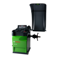
4. Carefully pull the gauge arm and read off the value
displayed on the measurement scale. (fig.54);
Fig. 26:
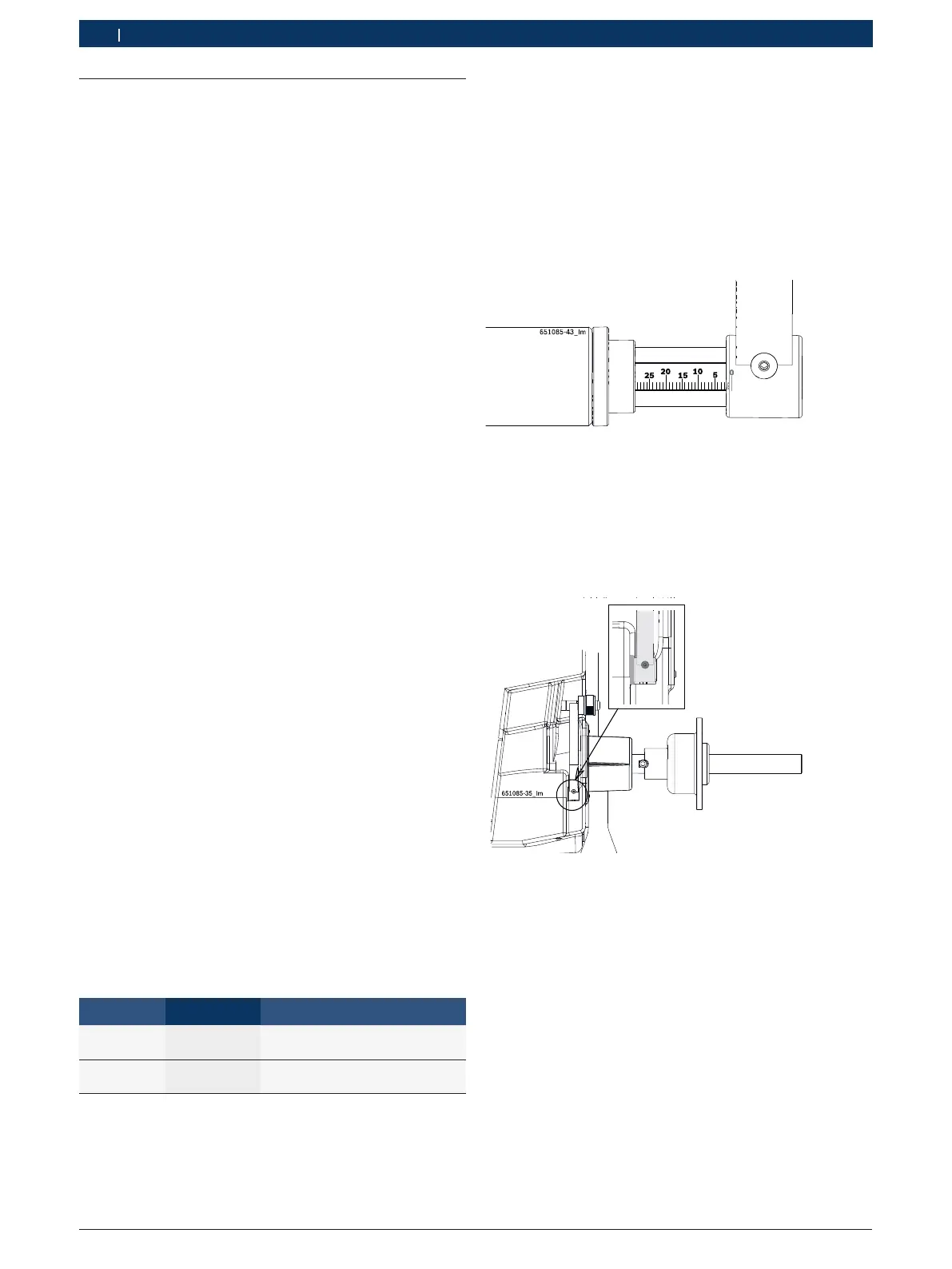
5. Move the vernier caliper to rest position.
i "Rest position" refers to the position in which the
gauge arm makes full contact with the lever (refer to
Fig. 55).
Fig. 27:
6. Use <-> or <+> to change the measured values.
The value is shown on the right-hand display.
7. Confirm with <RIM DISTANCE> (Fig.21).
D-2 appears in the left-hand display.
8. Use <-> or <+> to enter the value "200".
9. Pull out the vernier caliper to a distance of 200 mm
and hold in this position.
$ Confirm with <RIM DISTANCE> (Fig.21).
H-1 appears in the left-hand display.