EasyManuals Logo

Brocade Communications Systems FastIron X Series Hardware Installation Guide

Brocade Communications Systems FastIron X Series
216 pages
To Next Page IconTo Next Page
To Previous Page IconTo Previous Page
Page #164 background imageLoading...
Page #164 background image
152 Brocade FastIron X Series Chassis Hardware Installation Guide
53-1001723-02
Replacing the FSX and FSX 800 fan tray
6
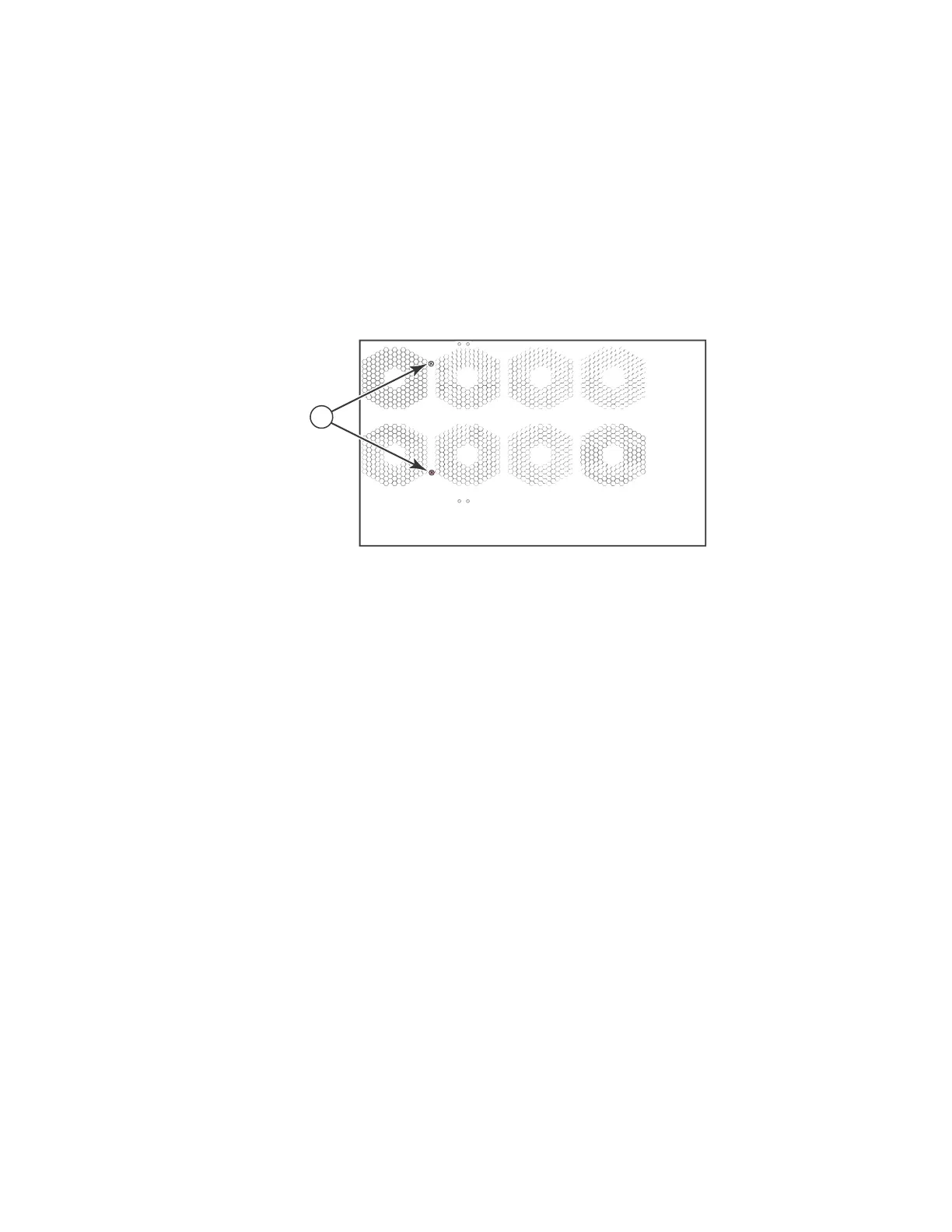
3. The FSX and FSX 800 ship with two extra screws installed in the right side of the chassis.
These screws secure the fan tray, protecting it from damage during shipment. These screws
should have been removed during installation. If these screws were not removed during
installation, you must remove them before replacing the fan tray. Figure 54 shows the location
of the screws.
To perform this task, you need a #2 Phillips-head screwdriver.
FIGURE 54 Removing the extra screws used for shipment
1 Shipping screws
1
Chassis front Chassis rear

Table of Contents

Other manuals for Brocade Communications Systems FastIron X Series

Questions and Answers:

Question and Answer IconNeed help?

Do you have a question about the Brocade Communications Systems FastIron X Series and is the answer not in the manual?

Brocade Communications Systems FastIron X Series Specifications

General IconGeneral
BrandBrocade Communications Systems
ModelFastIron X Series
CategorySwitch
LanguageEnglish

Related product manuals