EasyManuals Logo

Brocade Communications Systems FastIron X Series Hardware Installation Guide

Brocade Communications Systems FastIron X Series
216 pages
To Next Page IconTo Next Page
To Previous Page IconTo Previous Page
Page #185 background imageLoading...
Page #185 background image
Brocade FastIron X Series Chassis Hardware Installation Guide 173
53-1001723-02
Power supply specifications
7
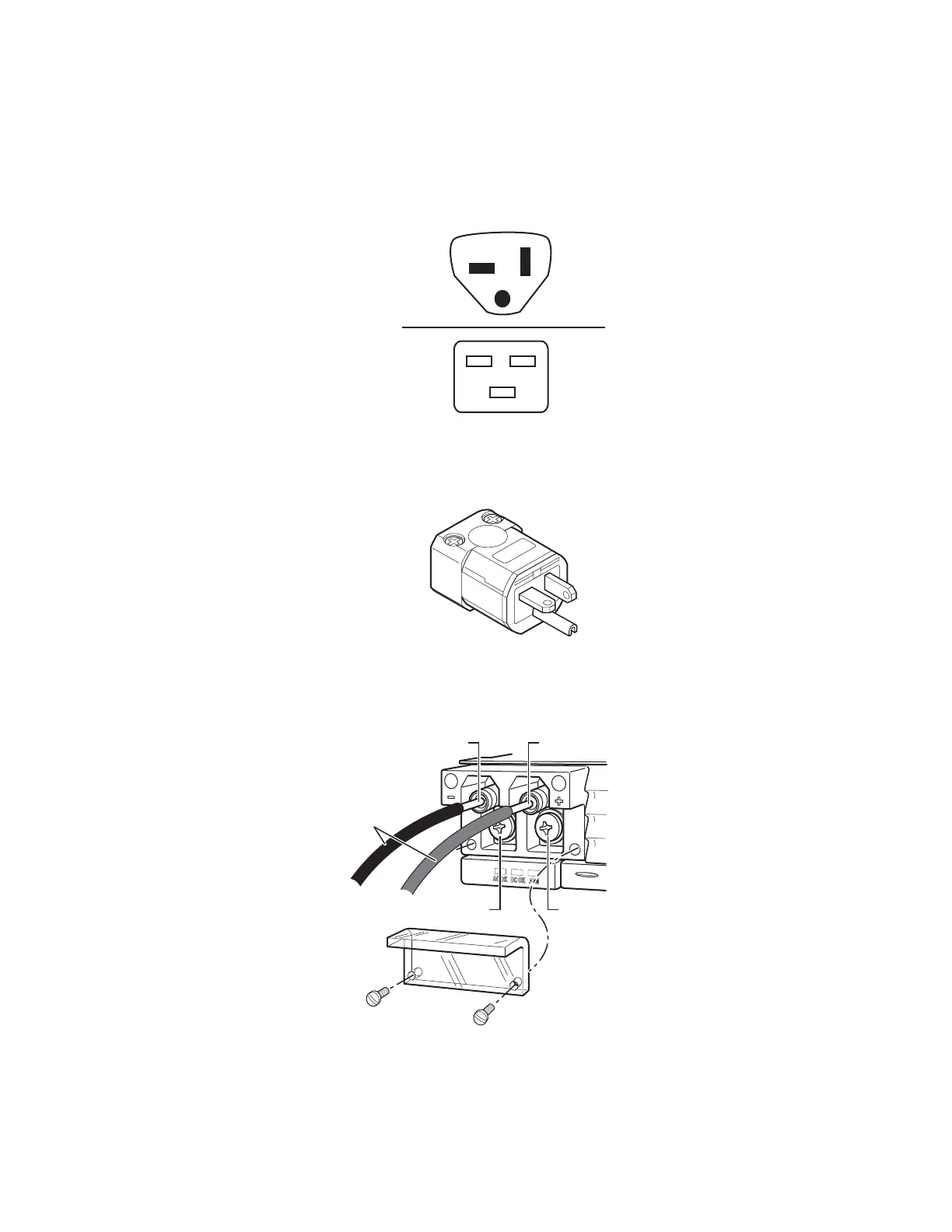
Figure 65 shows the power plug and connector for the SX-ACPWR-SYS and SX-ACPWR-POE power
supplies. The power cord is 2.5 meters in length.
FIGURE 65 AC power cable plug and input connector for SX-ACPWR-SYS and SX-ACPWR-POE
power supplies
Figure 66 shows the power plug for the SX-ACPWR2500-POE power supply.
FIGURE 66 AC power cable plug for SX-ACPWR2500-POE power supply
Figure 67 shows the DC connector for the SX-DCPWR-SYS and SX-DCPWR-POE power supplies.
FIGURE 67 DC power cables for SX-DCPWR-SYS and SX-DCPWR-POE power supplies
M
F
- 48 VDC Lead 48 RTN Lead
8 AWG Wire
Negative Terminal Screw
Terminal
Screw
Cover
Positive Terminal Screw

Table of Contents

Other manuals for Brocade Communications Systems FastIron X Series

Questions and Answers:

Question and Answer IconNeed help?

Do you have a question about the Brocade Communications Systems FastIron X Series and is the answer not in the manual?

Brocade Communications Systems FastIron X Series Specifications

General IconGeneral
BrandBrocade Communications Systems
ModelFastIron X Series
CategorySwitch
LanguageEnglish

Related product manuals