EasyManuals Logo

Brocade Communications Systems FastIron X Series Hardware Installation Guide

Brocade Communications Systems FastIron X Series
216 pages
To Next Page IconTo Next Page
To Previous Page IconTo Previous Page
Page #37 background imageLoading...
Page #37 background image
Brocade FastIron X Series Chassis Hardware Installation Guide 25
53-1001723-02
Hardware features
1
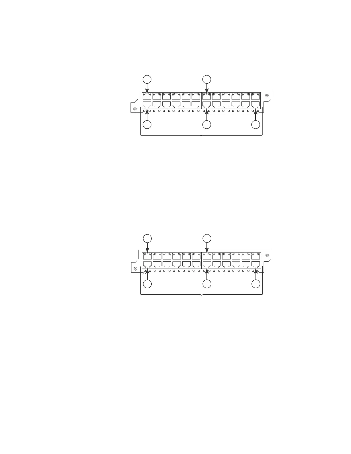
Figure 15 shows the front panel of the IPv4 24-port Gigabit Ethernet copper module.
FIGURE 15 IPv4 24-port Gigabit Ethernet copper module front panel
Figure 16 shows the front panel of the IPv6 24-port Gigabit Ethernet copper module.
FIGURE 16 IPv6 24-port Gigabit Ethernet copper module front panel
The front panel includes the following control features:
24 10/100/1000 copper ports
24 LEDs for port status
24 LEDs for Power over Ethernet (POE) status
1Port 1
2Port 2
13 Port 13
14 Port 14
24 Port 24
1Port 1
2Port 2
13 Port 13
14 Port 14
24 Port 24
424C
2 14 24
1
13
POE LEDs
624C
2
14 24
1
13
POE LEDs

Table of Contents

Other manuals for Brocade Communications Systems FastIron X Series

Questions and Answers:

Question and Answer IconNeed help?

Do you have a question about the Brocade Communications Systems FastIron X Series and is the answer not in the manual?

Brocade Communications Systems FastIron X Series Specifications

General IconGeneral
BrandBrocade Communications Systems
ModelFastIron X Series
CategorySwitch
LanguageEnglish

Related product manuals