Brookeld Engineering Labs., Inc. Page 12 Manual No. M/03-165-D0410
II. GETTING STARTED
II.1 Autozero
Before readings may be taken, the Viscometer must be Autozeroed. This action is performed
each time the power switch is turned on. (Note: If cable DVP-80 is connected for printer or
computer communication see section II.9). The display window on the Viscometer will guide
you through the procedure as follows:
Turn the power switch (located on the rear panel) to the ON position. This will result in
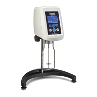
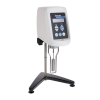
the screen display shown in Figure II-1 indicating that the DV-II+Pro viscometer is in the
standalone mode (is not connected to a computer).
BROOKFIELD DV-2+
PRO VISCOMETER
Figure II-1
After a few seconds, the following screen appears indicating the version of the operating
rmware (the built in program which controls the instrument) and a two-digit alphanumeric
code which indicates the Model number (see Table D2 in Appendix D; the code tells the spring
torque rating or the viscosity measurement range of your viscometer). For most DV-II+Pro
Viscometers, this information will be either “LV”, “RV” or “HB”:
BROOKFIELD DV-2+
RV V6.3
Figure II-2
No key press is required at this point. After a short time, the display will clear and the
following will be displayed:
REMOVE SPINDLE
PRESS ANY KEY
Figure II-3
After removing the spindle and pressing any key, the DV-II+Pro begins its Autozero. The
screen will ash “Autozeroing.”
After approximately 15 seconds, the display shows the screen in Figure II-4:
REPLACE SPINDLE
PRESS ANY KEY
Figure II-4
 Loading...


