Do you have a question about the Brookfield RVDV-II+Pro and is the answer not in the manual?
| Brand | Brookfield |
|---|---|
| Model | RVDV-II+Pro |
| Category | Measuring Instruments |
| Language | English |
Lists all parts included with the viscometer and instructions for checking them.
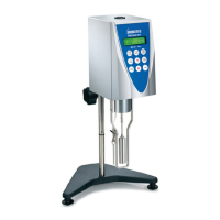
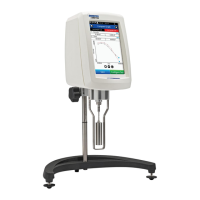
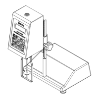
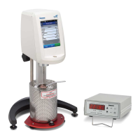
Visual illustration of the viscometer, stand, and optional accessories.
Details power requirements, cord colors, and voltage specifications for the instrument.
Outlines technical details like speed options, weight, and accuracy.
Provides step-by-step instructions for setting up the viscometer and stand.
Explains safety symbols and general precautions for safe operation.
Describes the purpose and operation of each control key on the viscometer.
Provides guidelines for cleaning the instrument and its components.
Procedure to initialize the viscometer before taking measurements.
How to select and enter the correct spindle code for accurate readings.
Guide to choosing, setting, and starting the viscometer at desired speeds.
How to cycle through and view different measurement parameters on the display.
Function to automatically determine the maximum possible viscosity reading.
Explains how the viscometer indicates readings outside the operational range.
How the measured temperature is displayed and its accuracy.
Instructions for printing measurement data to an attached printer.
How to connect the viscometer to a PC for external control.
General procedure for performing viscosity measurements with the instrument.
Features for unattended measurements using time-based settings.
Overview of configuration and special functions available in the Options menu.
Accessing and configuring instrument settings like temperature and units.
Setting the temperature display to Centigrade or Fahrenheit.
Configuring the display and print units to CGS or SI.
Choosing between Sequential, Interleave, or Custom speed sets.
Selecting the serial or parallel port for printer output.
Enabling and configuring the rolling average feature for data smoothing.
Setting up unattended measurement modes like Time to Stop and Time to Torque.
Configuring a measurement to run for a specific duration.
Configuring a measurement to run until a target torque is reached.
Setting the time interval for continuous data printing.
Enabling high-speed output for data acquisition software.
Transferring pre-programmed test sequences to the viscometer.
Executing downloaded B.E.V.I.S. programs on the viscometer.
Introduction to the scripting language for programming the viscometer.
Explanation of the command codes used for creating programs.
Step-by-step guide to using the DVLOADER software to build programs.
Instructions for transferring created programs from PC to the viscometer.
Sample test programs for common viscosity measurement scenarios.
Software for data collection, graphical analysis, and file management.
Software for PC-controlled operation and advanced data analysis.
Features for enabling and using the electronic gap setting function.
Procedures for setting up the cone/plate viscometer with water bath.
Detailed steps for adjusting the gap between cone and plate.
Procedures to verify the instrument's calibration using standard fluids.
Test results and analysis for low-viscosity liquids.
Discusses how accessories can impact measurement accuracy and tolerance.
Explains fluid behavior and classification like Newtonian and Non-Newtonian.
Discusses factors related to the instrument and spindle affecting readings.
Standard calibration steps for common spindle types.
Verification of calibration when using the Small Sample Adapter.
Calibration steps specific to the Thermosel temperature control system.
Calibration steps for UL or DIN UL adapter accessories.
Troubleshooting steps for when the viscometer spindle fails to turn.
Solutions for spindles that wobble or appear bent during rotation.
Procedure to check the internal mechanics of the viscometer.
Steps to diagnose and correct inconsistent or wrong measurement values.
Troubleshooting for issues where the viscometer does not reset to zero.
Addressing problems with fluctuating or unstable readings on the display.
Steps to fix issues where the recorder or printer is not receiving data.
Correcting problems with incorrect polarity or direction of recorder output.
Troubleshooting PC connection issues and software communication.




 Loading...